3. Servicing and Conversion
3.1 Servicing 3.2 Conversion
IMPORTANT
BEFORE ATTEMPTING ANY SERVICING, ENSURE
THAT THE GAS ISOLATING COCK IS TURNED OFF
AND CANNOT BE INADVERTENTLY TURNED ON.
ENSURE ALSO THAT THE ELECTRICITY SUPPLY IS
DISCONNECTED.
AFTER ANY SERVICING OR EXCHANGE OF GAS
CARRYING COMPONENTS — ALWAYS CHECK
FOR GAS SOUNDNESS!
Notes: 1. When replacing wiring connections refer to the wiring
2. When any threaded gas connection is disturbed for any
reason, the threads must be resealed with appropriate
gas leak prevention sealant that is suitable for the type of
gas. Unified Brands/ Groen recommends gas sealant
compound such as Locktite® 243 or Unified Brands part
number 122002.
diagram in the unit or this manual.
3.1.1 After Servicing
a) Test for gas soundness as specified in IGE/UP1
b) If leaks are found, disconnect the mating parts, clean
the threads and apply recommended sealant as
specified in paragraph 3.1 Note 2 above.
as appropriate after any gas connection has been
disturbed.
c) Check for correct operation as appropriate (see
Installation, Section 1.5).
3.1.2 Regular Servicing Procedures
The following must be checked at regular intervals:
a) Burners
Clean the burners periodically to maintain
maximum performance. Burners are best
cleaned with a stiff bristle brush, or if necessary
with a wire brush. Take care not to damage the
burner.
Clean the injector orifice with a wooden splinter or
toothpick. Avoid metal reamers, which may
distort or increase the orifice size.
WARNING - Do not leave any wood splinter or
bristles from brush in the burner or injector. Fire
could result.
b) Gears and Bearings
The gear housing has been fitted for proper
lubrication of moving parts. Since the gears do
not run in oil, periodic lubrication with grease is
essential. Frequency of lubrication depends on
operating conditions, but should occur at least
once every six months. Groen recommends the
use of a Number Two grade LGI lithium grease.
Add grease through the Zerk fittings on the gear
housing until grease flows out of the bearings
around the trunnion shaft. Place a liberal amount
of grease on the gear to cover the arc that is in
contact with the worm gear.
3.2.1 After Conversion
a) Test for gas soundness as specified in IGE/UP1
b) If leaks are found, disconnect the mating parts,
clean the threads and apply recommended sealant
as specified in paragraph 3.1 Note 2.
as appropriate after any gas connection has been
disturbed.
Notes:
To change the type of gas used (e.g G20 to G31 or inverse)
following parts should be changed:
1. Burner injectors. See instruction 3.13 on page 16.
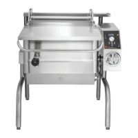
2. Igniter tube injector. This is inserted inside the igniter tube as
shown on below.
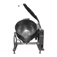
3. Gas valve spring. Install per instructions supplied with the
spring package as shown below.
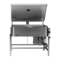
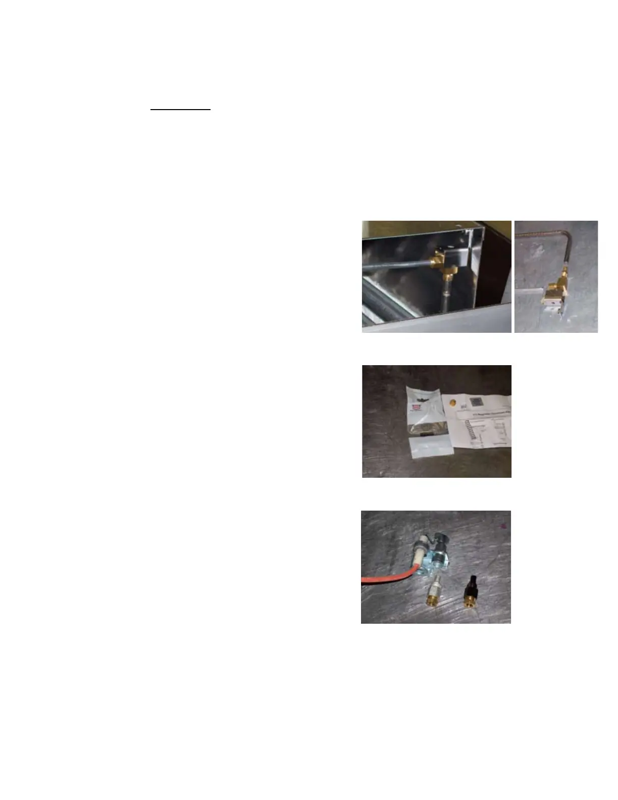
4. Pilot orifice. Insert the black shaded orifice for G31 gas as
shown below. The light colored orifice is for G20 gas.
5. Data plate with correct rate and gas manifold
pressure information.
1. See Para 1.5, page 9 for important information. VERIFY
THE TYPE OF GAS TO BE USED. In the countries listed
in Paragraph 1.5, all conversions must be for approved gas.
2. All threaded gas connections must be sealed as specified
in paragraph 3.1, Note #2.
 Loading...