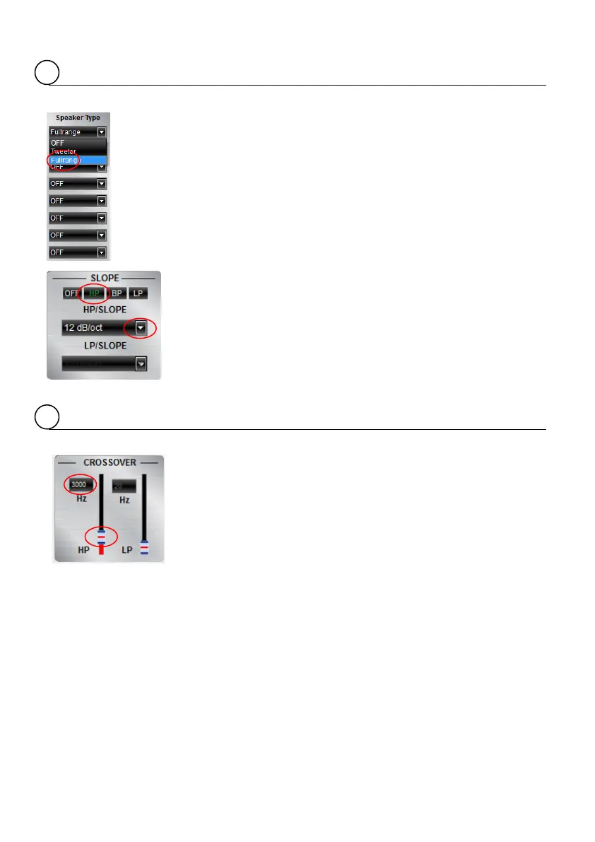
SLOPE
CROSSOVER
Adjustment of the crossover
Before choosing the filter, a
must be defined in window 3.
When the setup consists of a front system connected to channel A/B and
a rear speaker system connected to channel C/D, the
entry
should be selected. According to the speakers and listeners request a
high pass filter (HP) can be activated at the
window.
High pass (
) / Bandpass (
) and low pass (
) can be chosen at the
window for the selected channel(s).
A slope of 6 to 48 dB/oct can be selected at the drop down menu.
The higher the selected value the steeper the slope starting at the
crossover frequency.
Adjusting the cutoff frequency
The filters can be adjusted continuously from 20 – 20000 Hz.
The controls can only be used if a filter (Slope/6) has been selected
first.
: If a filter has been selected, it is possible to adjust the crossover
frequency directly with the cursor at the frequency chart (8). Click and
hold the red (HPF) or blue (LPF) dot with the cursor and move it to the
desired point on the frequency chart.
Instead of using the crossover control, it is possible to adjust the
crossover point by typing the required value directly into the box above
and confirm with >ENTER< or by using the up/down cursor buttons.