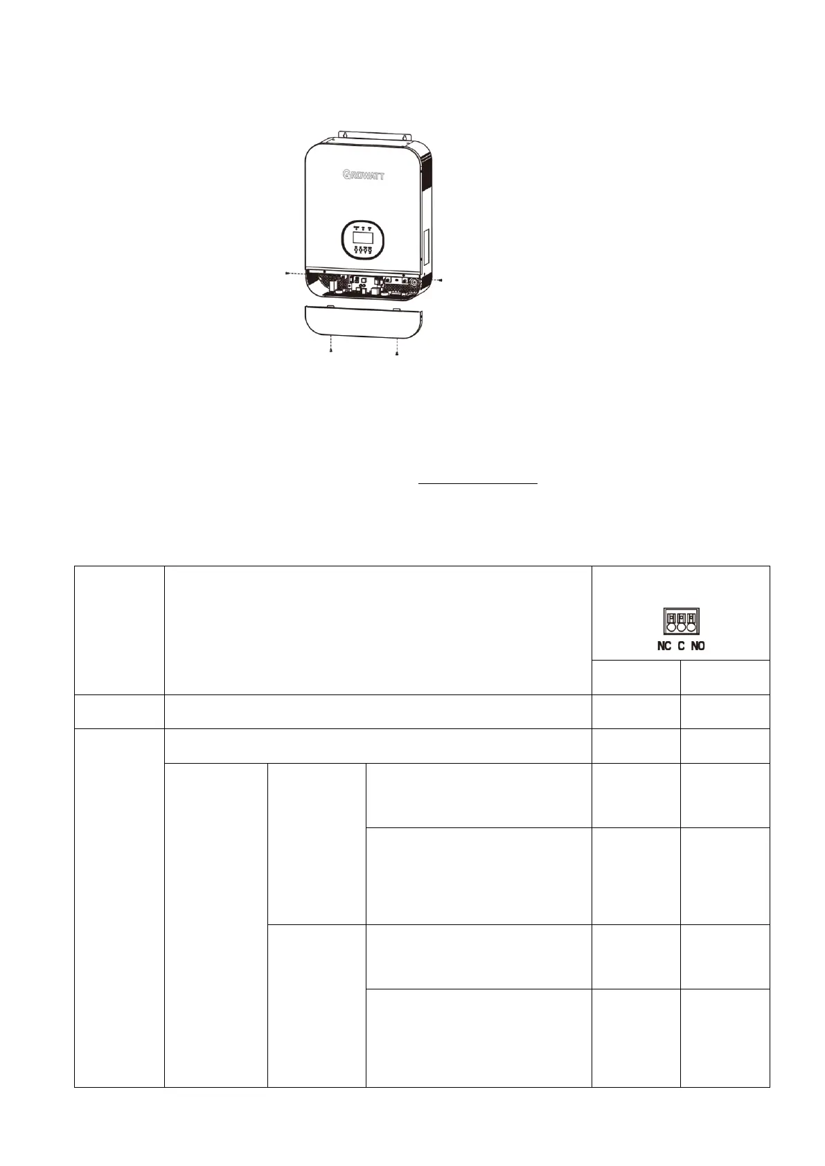
Final Assembly
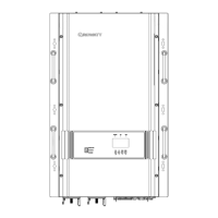
After connecting all wiring, please put bottom cover back by screwing two screws as shown below.
Communication Connection
Please use supplied communication cable to connect to inverter and PC. Follow on-screen instruction to install
the monitoring software. For the detailed software operation, please check user manual of software. The
monitoring software is downloadable from our website www.ginverter.com.
Dry Contact Signal
There is one dry contact(3A/250VAC) available on the rear panel. It could be used to deliver signal to external device
when battery voltage reaches warning level.
Unit is off and no output is powered
Output is powered from Utility
Output is
powered from
Battery or Solar
Program 01 set
as Utility first
Battery voltage (SOC)< Low DC
warning voltage(SOC)
Battery voltage(SOC) > Setting
value in Program 13 or battery
charging reaches floating stage
Program 01 is
set as SBU or
Solar first
Battery voltage (SOC)< Setting
value in Program 12
Battery voltage (SOC)> Setting
value in Program 13 or battery
charging reaches floating stage
 Loading...