3.7 Communication Connection
Please use supplied communication cable to connect to inverter and PC. Insert bundled CD into a computer and
follow on-screen instruction to install the monitoring software. For the detailed software operation, please
check user manual of software inside of CD.
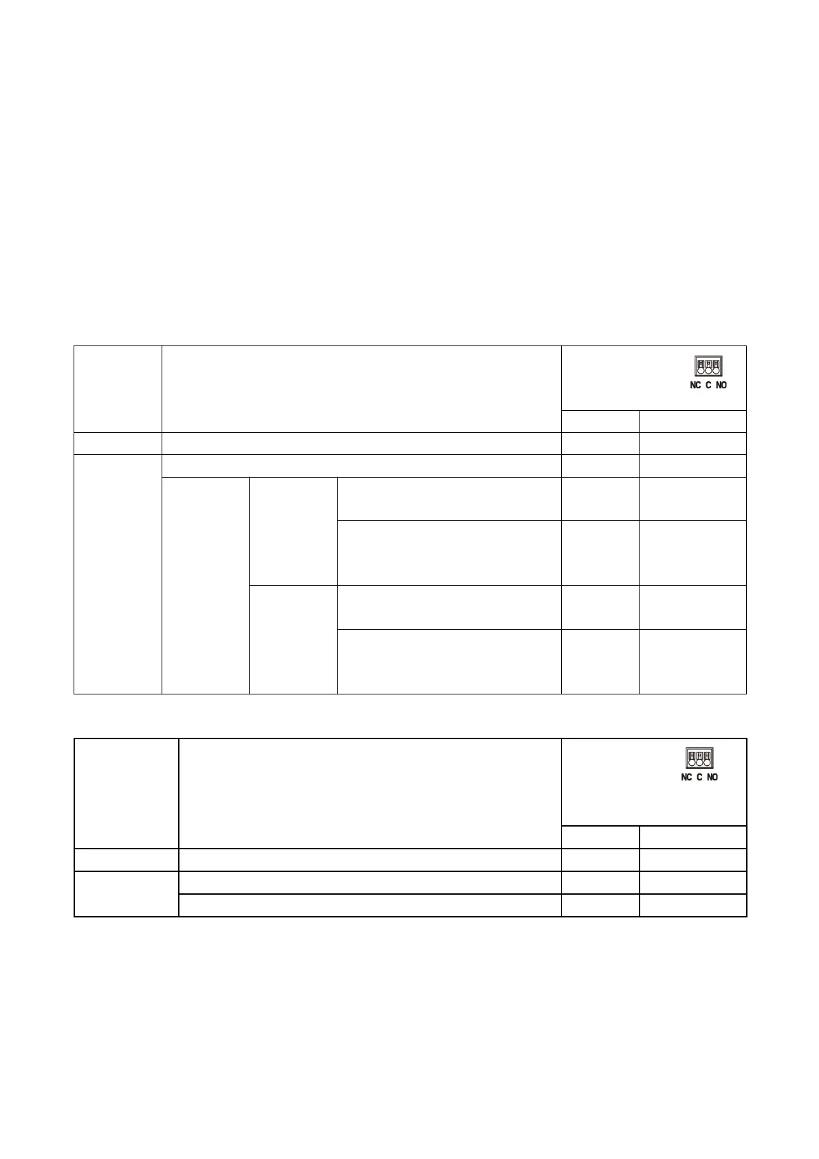
3.8 Dry Contact Signal
There is one dry contact available on the rear panel. When program 24 is set as “disable”, it could be used to
deliver signal to external device when battery voltage reaches warning level. When program 24 is set as
“enable” and the unit is working in battery mode, it could be used to trigger the grounding box to connect
neutral and grounding of AC output together.
When program 24 is set as “disable” (default setting):
Unit is off and no output is powered.
Output is powered from Utility.
Output is
powered
from
Battery or
Solar.
Battery voltage < Low DC warning
voltage
Battery voltage > Setting value in
Program 13 or battery charging
reaches floating stage
Program 01
is set as
SBU or
Solar first
Battery voltage < Setting value in
Program 12
Battery voltage > Setting value in
Program 13 or battery charging
reaches floating stage
When program 24 is set as “enable”:
Unit is off and no output is powered.
Unit works in standby mode, line mode or fault mode
Unit works in battery mode or power saving mode
 Loading...