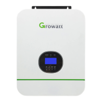
PV Connection
Please refer to user manual of single unit for PV Connection on Page 12.
CAUTION: Each inverter should connect to PV modules separate.
LCD Setting and Display
Refer to Program 23 on Page 20
Parallel in Single Phase
Step 1: Check the following requirements before commissioning:
Correct wire connection
Ensure all breakers in Line wires of load side are open and each Neutral wires of each unit are connected
together.
Step 2: Turn on each unit and set “PAL” in LCD setting program 23 of each unit. And then shut down all units.
Note: It’s necessary to turn off switch when setting LCD program. Otherwise, the setting can not be programmed.
Step 3: Turn on each unit.
LCD display in Master unit
LCD display in Slave unit
Note: Master and slave units are randomly defined.
Step 4: Switch on all AC breakers of Line wires in AC input. It’s better to have all inverters connect to utility at the
same time. If not, it will display warning 15.
LCD display in Master unit
LCD display in Slave unit
Step 5: If there is no more fault alarm, the parallel system is completely installed.
Step 6: Please switch on all breakers of Line wires in load side. This system will start to provide power to the load.
Parallel in Three Phase
Step 1: Check the following requirements before commissioning:
Correct wire connection
Ensure all breakers in Line wires of load side are open and each Neutral wires of each unit are connected
together.
Step 2: Turn on all units and configure LCD program 23 as P1, P2 and P3 sequentially. Then shut down all units.
Note: It’s necessary to turn off switch when setting LCD program. Otherwise, the setting can not be
programmed.