English (GB)
2
English (GB) Functional profile and user manual
Original functional profile and user manual.
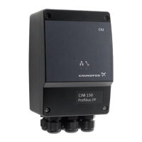
This functional profile describes Grundfos PROFINET and
PROFIBUS for boosters.
CONTENTS
Page
1. General information
1.1 Hazard statements
The symbols and hazard statements below may appear in
Grundfos installation and operating instructions, safety
instructions and service instructions.
The hazard statements are structured in the following way:
1.2 Notes
The symbols and notes below may appear in Grundfos
installation and operating instructions, safety instructions and
service instructions.
1. General information
2
1.1 Hazard statements
2
1.2 Notes
2
2. Introduction
3
2.1 About this functional profile
3
2.2 PROFIBUS DP-V0
3
2.3 PROFIBUS DP-V1
3
2.4 Assumptions
3
2.5 Definitions and abbreviations
3
3. System description
4
3.1 PROFIBUS DP, CIM 150
4
3.2 PROFINET IO, CIM 500
5
4. Specifications
6
4.1 CIM module
6
4.2 CIM 150 PROFIBUS DP
6
4.3 CIM 500 PROFINET IO
6
5. PROFIBUS DP, CIM 150 setup
7
5.1 PROFIBUS bus topology
7
5.2 CIM 150 PROFIBUS module
7
5.3 Connecting the PROFIBUS
7
5.4 Setting the PROFIBUS address
8
5.5 Termination resistors
8
5.6 Status LEDs
8
5.7 Communication watchdog
8
5.8 Reaction to PLC "Stop button"
8
6. PROFINET IO, CIM 500 setup
9
6.1 Connecting the ethernet cable
9
6.2 Setting the Industrial Ethernet protocol
9
6.3 Setting the IP addresses
9
6.4 Establish a connection to the webserver
10
6.5 Status LEDs
10
6.6 DATA and LINK LEDs
10
7. Detailed description of data modules
11
7.1 Data types
11
7.2 Control module (ControlModule, module 2)
11
7.3 Status module (StatusModule, module 1)
14
7.4 Illustration of closed-loop control
16
7.5 Direct bus control of pumps (ControlPumps, module
50)
16
7.6 Change feedback sensor type (SelectFeedbackSensor
module 57)
16
7.7 Alarms and warnings
17
7.8 Measurement modules
18
7.9 Zone pump modules (ZonePumpModule, modules 29
to 34)
22
7.10 Zone pump extension modules
(ZonePump#ExtModule, modules 35 to 40)
23
7.11 Pilot pump module (PilotPumpModule, module 55)
23
7.12 Backup pump module (BackupPumpModule, module
56)
23
7.13 Device identification (DeviceIdentification, module 47)
24
8. Product simulation
25
8.1 CIM 150 product simulation
25
8.2 CIM 500 Product Simulation
25
9. Fault finding the product
26
9.1 CIM/CIU 150
26
9.2 CIM/CIU 500
27
10. PROFIBUS address
28
11. Disposal
28
Read this document before installing the product.
Installation and operation must comply with local
regulations and accepted codes of good practice.
DANGER
Indicates a hazardous situation which, if not avoided,
will result in death or serious personal injury.
WARNING
Indicates a hazardous situation which, if not avoided,
could result in death or serious personal injury.
CAUTION
Indicates a hazardous situation which, if not avoided,
could result in minor or moderate personal injury.
SIGNAL WORD
Description of hazard
Consequence of ignoring the warning.
- Action to avoid the hazard.
Observe these instructions for explosion-proof
products.
A blue or grey circle with a white graphical symbol
indicates that an action must be taken.
A red or grey circle with a diagonal bar, possibly with
a black graphical symbol, indicates that an action
must not be taken or must be stopped.
If these instructions are not observed, it may result in
malfunction or damage to the equipment.
Tips and advice that make the work easier.

 Loading...