English (GB)
4
3. System description
The system diagrams give an overview for the different
technologies of how to connect the module or unit to the
Grundfos booster system that you connect to a PROFIBUS/
PROFINET network.
The booster system controls and monitors a number of pumps, all
connected with RS-485 cables (Sub-GENIbus).
Note that the Hydro MPC and Control MPC are available in two
variants, with a CU 351 or a CU 352 control unit. They have
different CIM/CIU connections as described below.
CIM solution
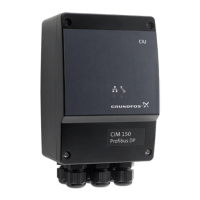
CIM 150 is an add-on communication module that you install into
the back of CU 352 Hydro MPC or CU 323 Hydro Multi-B, using a
10-pin connection. In this setup, the booster system supplies
power to the module. See fig. 1 and fig. 4.
CIU solution
CIU 150 is a unit with a power supply module and a CIM module.
You can mount it either on a DIN rail or on a wall. See fig. 2 and
fig. 5.
You use CIU 150 with earlier products:
• CU 351 MPC
• Multi-E model G
Further, you must fit CU 351 MPC with an add-on module for the
external GENIbus connection to connect to the unit.
3.1 PROFIBUS DP, CIM 150
Fig. 1 Example of a CIM 150 solution. The module is
installed inside the CU352 controller
Fig. 2 Example of a CIU 150 solution for Hydro Multi-E,
model G
Fig. 3 Example of a CIM 150 solution for Hydro Multi-E
model H and later. Pumps connected via built-in radio
communication (Grundfos Glowpan)
The example for Multi-E model H and later is identical for TPED
model H and later and MAGNA3-D. In all cases, mount the CIM
module in the master pump placed to the left.
For the purpose of redundancy, you can mount a second CIM
module in pump 2 for TPED and Multi-E (not MAGNA3-D). In that
case, all writings from the Profibus master must be send to both
CIM modules.
TM04 2297 2208
PROFIBUS DP
Hydro MPC
(CU 352)
1 2 34 56 7
8
9
CIM 150
Sub-GENIbus
RS-485
TM04 2608 2608TM07 0146 4317
CIU 150
External
GENIbus
RS-485
PROFIBUS DP
CRE with
Hydro Multi-E
add-on
Sub-GENIbus RS-485

 Loading...