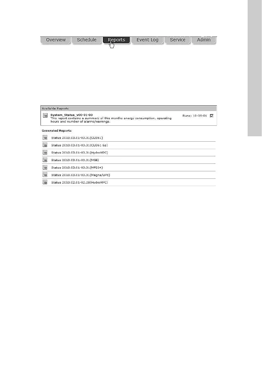
English (GB)
13
7. CIM 500 Modbus TCP setup
7.1 Connecting the Ethernet cable
Use RJ45 plugs and Ethernet cable. Connect the cable shield to
protective earth at both ends.
Maximum cable length
CIM 500 is designed for flexible network installation. The built-in
two-port switch makes it possible to daisy chain from product to
product without the need of additional Ethernet switches. The last
product in the chain is only connected to one of the Ethernet
ports. Each Ethernet port has its own MAC address.
Fig. 23 Example of Industrial Ethernet network
Fig. 24 Example of Ethernet connection
7.2 Setting the Industrial Ethernet protocol
The CIM 500 Ethernet module has a rotary switch for selection of
the Industrial Ethernet protocol. See fig. 25.
Fig. 25 Selecting the Industrial Ethernet protocol
7.3 Setting the IP addresses
The CIM 500 Ethernet module is by default set to a fixed IP
address. It is possible to change the IP address settings from the
built-in webserver.
WARNING
Electric shock
Death or serious personal injury
- Connect CIM 500 only to SELV or SELV-E circuits.
It is important to connect the cable shield to earth
through an earth clamp or to connect the cable shield
to earth in the connector.
Speed
[Mbits/s]
Cable type
Maximum cable length
[m/ft]
10 CAT5 100/328
100 CAT5e, CAT6 100/328
TM05 6435 4711
TM05 7431 1013
Ethernet
switch
CIM
500
CIM
500
CIM
500
CIM
500
Pos. Description Designation
1 Industrial Ethernet RJ45 connector 1 ETH1
2 Industrial Ethernet RJ45 connector 2 ETH2
3 Rotary switch for protocol selection SW1
4 Data activity LED for connector 1 DATA1
5 Link LED for connector 1 LINK1
6 Data activity LED for connector 2 DATA2
7 Link LED for connector 2 LINK2
8
Green and red status LED for Ethernet
communication
LED1
9
Green and red status LED for internal
communication between the module and
the booster system.
LED2
TM05 7431 1013
Pos. Description
0 PROFINET IO (default)
1 Modbus TCP
2 BACnet IP
3 EtherNet/IP
4 GRM IP (requires a contract with Grundfos)
5..E
Reserved, LED1 will be permanently red to indicate an
invalid configuration.
F
Reset to factory default.
Note that the rotary switch must be set in this position
for 20 seconds to reset to factory default. During this
period, LED1 flashes red and green at the same time to
indicate that a reset will occur.
Every change of the rotary switch while the module is
powered on will cause the module to restart.
Default IP settings
used by the
webserver
IP address: 192.168.1.100
Subnet mask: 255.255.255.0
Gateway: 192.168.1.1
IP settings for
Modbus TCP
Make the settings via the webserver