Pos. Component
1 Diaphragm tank
2 Pressure gauge 0-145 psi (0-10 bar)
3 Five-way fitting with integrated non-return valve
4 CME pump
5 Pressure sensor
4.1 Handling the product
The packaging is specifically designed to protect the pump from
damage.
Do not remove the packaging from the pump until
installation.
• During unpacking and before installation, make sure that the
pump is not dropped or mishandled.
5. Mechanical installation
WARNING
‐ Installation and operation must comply with local
regulations and accepted codes of good practice.
WARNING
‐ All electrical work should be performed by a qualified
electrician in accordance with the latest edition of the
National Electrical Code, local codes, and regulations.
WARNING
‐ Verify that the electrical supply has been switched OFF
before making any connections.
‐ The pump should not be connected to the electrical
system until it has been properly installed in the pipe
system.
We recommend that installation is carried out by skilled personnel
with technical qualifications required by the specific legislation in
force.
The term skilled personnel means persons whose training,
experience, and instruction, as well as their knowledge of the
respective standards and requirements for accident prevention and
working conditions, have been approved by the person in charge of
plant safety, authorizing them to perform all the necessary activities
during which they are able to recognize and avoid all dangers.
5.1 Mounting the product
• Secure the pump to a solid foundation by bolts through the
holes in the flange or the base plate.
5.2 Cable entries
The motor has four M20 screwed cable entries fitted with blind
plugs from the factory.
The following cable glands are included:
• 2 x M20 cable glands, cable diameter ∅5 mm
• 1 x M20 cable glands, cable diameter ∅7-14 mm.
5.3
Motor cooling
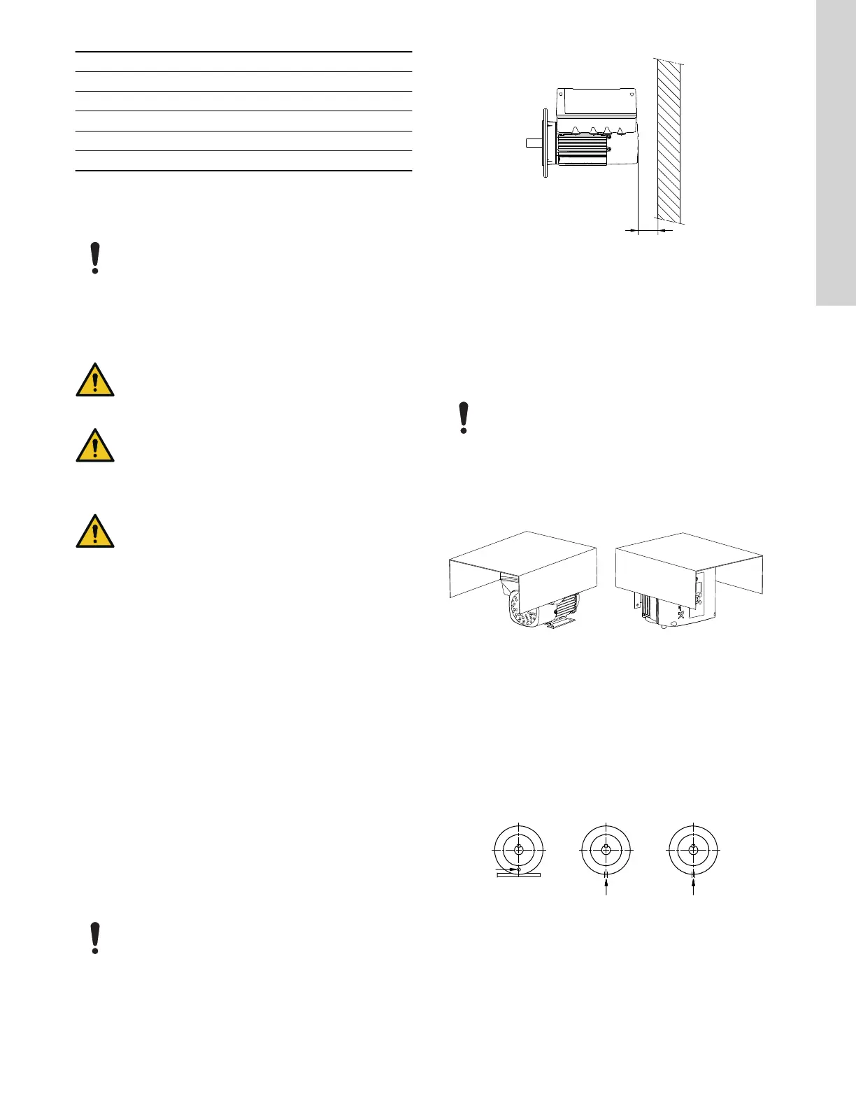
In order to ensure sufficient cooling of the motor, the
distance (D) between the end of the fan cover and a wall
or other fixed objects must always be at least 2 inches (50
mm) irrespective of motor size.
TM055236
Minimum distance (D) from the motor to a wall or other fixed
objects
Related information
12.1.5 Motor cooling
5.4 Outdoor installation
When installed outdoors, the motor must be provided with a suitable
cover to avoid condensation on the electronic components.
When fitting a cover to the motor, observe the guidelines
in section Motor cooling.
The cover must be sufficiently large to ensure that the motor is not
exposed to direct sunlight, rain, or snow. Grundfos does not supply
covers. Therefore, we recommend that you have a cover built for
the specific application. In areas with high air humidity, we
recommend enabling the built-in standstill heating function.
TM053496
Examples of covers (not supplied by Grundfos)
5.5 Drain holes
When the motor is installed in moist surroundings or areas with high
air humidity, the bottom drain hole should be open.
The enclosure class of the motor will then become lower. The open
drain hole helps to prevent condensation in the motor as it will make
the motor self-vent and allow water and humid air to escape.
The motor has a plugged drain hole on the drive side. The flange
can be turned 90 ° to both sides or 180 °.
TM029037
Related information
12.1.4 Air humidity
7
English (US)

 Loading...


