15
English (US)
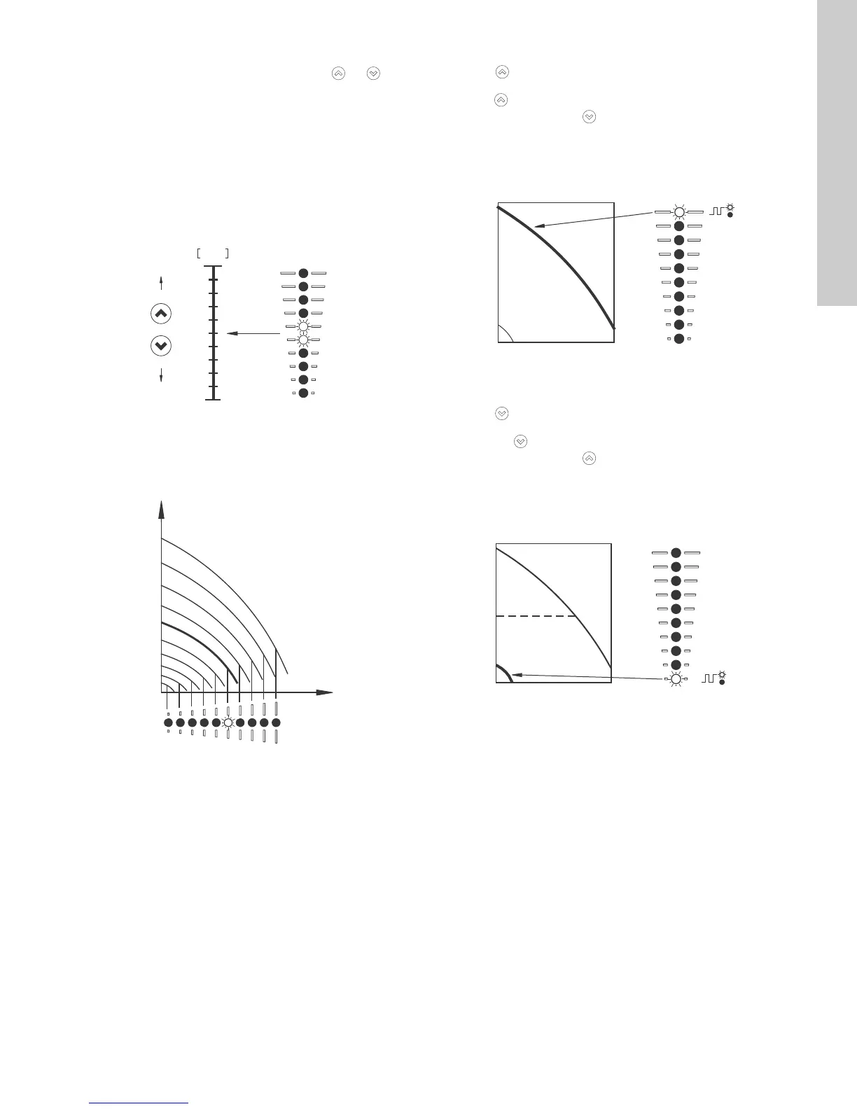
10.1.1 Setpoint setting
Set the desired setpoint of the pump by pressing or .
The light fields on the control panel will indicate the setpoint set.
Pump in constant-pressure control mode
The following example applies to a pump in an application where
a pressure sensor gives a feedback to the pump. If the sensor is
retrofitted to the pump, it must be set up manually as the pump
does not automatically register a connected sensor.
Figure 20 shows that the light fields 5 and 6 are activated,
indicating a desired setpoint of 3 bar with a sensor measuring
range from 0 to 6 bar. The setting range is equal to the sensor
measuring range.
Fig. 20 Setpoint set to 3 bar, constant-pressure control mode
Pump in constant-curve control mode
In constant-curve control mode, the pump performance will lie
between the max. and min. curve of the pump. See fig. 21.
Fig. 21 Pump in constant-curve control mode
Setting to max. curve:
•Press
continuously to change over to the max. curve of
the pump (top light field flashes). When the top light field is on,
press
for 3 seconds until the light field starts flashing.
• To change back, press
continuously until the desired
setpoint is indicated.
Example: Pump set to max. curve.
Figure 22 shows that the top light field is flashing, indicating max.
curve.
Fig. 22 Max. curve duty
Setting to min. curve:
•Press
continuously to change over to the min. curve of the
pump (bottom light field flashes). When the bottom light field is
on, press
for 3 seconds until the light field starts flashing.
• To change back, press continuously until the desired
setpoint is indicated.
Example: Pump set to min. curve.
Figure 23 shows that the bottom light field is flashing, indicating
min. curve.
Fig. 23 Min. curve duty
TM05 4894 3512TM05 4895 2812
TM05 4896 2812TM05 4897 2812
 Loading...


