27
English (US)
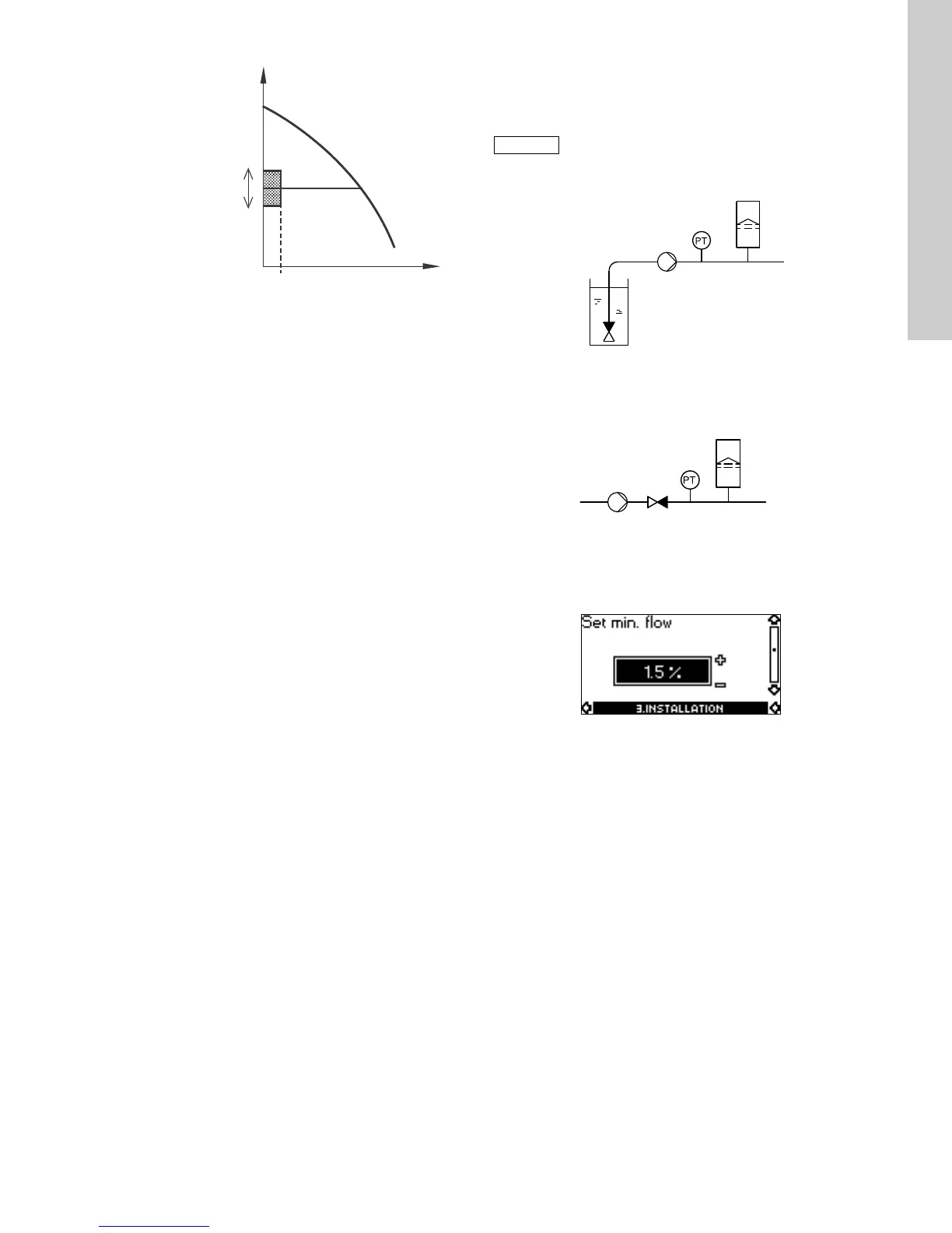
Fig. 31 Difference between start and stop pressures (∆H) and
minimum flow (Q
min
)
In start/stop operation, the pressure will vary between the start
and stop pressures. See fig. 31.
In "User-defined" mode, ∆H has been factory-set to 10 % of the
actual setpoint. ∆H can be set within the range from 5 to 30 % of
actual setpoint.
The pump will change to start/stop operation if the flow becomes
lower than Q
min
.
Q
min
is set in % of the rated flow of the pump (see pump
nameplate).
In "User-defined" mode, Q
min
has been factory-set to 10 % of
rated flow.
Low-flow detection
Low flow can be detected in two ways:
1. A built-in "low-flow detection function" which is active if none
of the digital inputs are set up for flow switch.
2. A flow switch connected to one of the digital inputs.
1. Low-flow detection function:
The pump will check the flow regularly by reducing the speed
for a short time. If there is no or only a small change in
pressure, this means that there is low flow. The speed will be
increased until the stop pressure (actual setpoint + 0.5 x ΔH)
is reached and the pump will stop. When the pressure has
fallen to the start pressure (actual setpoint - 0.5 x ΔH), the
pump will restart.
– If the flow is higher than the set minimum flow (Q
min
), the
pump will return to continuous operation at constant
pressure.
– If the flow is still lower than the set minimum flow (Q
min
), the
pump will continue in start/stop operation until the flow is
higher than the set minimum flow (Q
min
). When the flow is
higher than the set minimum flow (Q
min
), the pump will
return to continuous operation.
2. Flow switch:
When the digital input is activated for more than 5 seconds
because there is low flow, the speed will be increased until the
stop pressure (actual setpoint + 0.5 x ΔH) is reached, and the
pump will stop. When the pressure has fallen to start
pressure, the pump will restart. If there is still no flow, the
pump will quickly reach the stop pressure and stop. If there is
flow, the pump will continue operating according to the
setpoint.
Operating conditions for the low-flow stop function
It is only possible to use the stop function if the system
incorporates a pressure sensor, a non-return valve and a
diaphragm tank.
Fig. 32 Position of the non-return valve and pressure sensor in
system with suction lift operation
Fig. 33 Position of the non-return valve and pressure sensor in
system with a positive inlet pressure
Set min. flow
Set the minimum flow (Q
min
) in this display. This setting
determines at which flow rate the system is to change from
continuous operation at constant pressure to start/stop operation.
The setting range is 5 to 30 % of rated flow.
Factory setting: 10 %.
TM05 6079 4512
Stop pressure
Start pressure
The non-return valve must always be installed
before the pressure sensor. See figs 32 and 33.
TM03 8582 1907TM03 8583 1907
Pressure sensor
Diaphragm tank
Non-return
valve
Pump
Diaphragm tank
Pressure sensor
Pump Non-return valve
 Loading...


