Rated flow of pump
[gpm (m
3
h)]
CRE pump
Typical diaphragm
tank size
[gal (liter)]
0-26 (0 - 5.9) 1s, 1, 3 2 (7.6)
27-105 (6.1 - 23.8) 5, 10, 15 4.4 (16.7)
106-176 (24.2 - 40) 20, 32 14 (53.0)
177-308 (40.2 - 70.0) 45 34 (128.7)
309-440 (70.2 - 99.9) 64, 90 62 (234.7)
441-750 (100-170) 120, 150 86 (325.5)
If a diaphragm tank of the above size is installed in the system, the
factory setting of ΔH is the correct setting.
If the tank installed is too small, the pump will start and stop too
often. This can be remedied by increasing ΔH.
5.4.9 Flow limit for the stop function
Flow limit for the stop function only works if the system is
not set up for flow switch.
In order to set at which flow rate the system is to go from
continuous operation at constant pressure to start/stop operation,
select among these four values of which three are preconfigured
flow limits:
• Low
• Normal
• High
• Custom.
The default setting of the pump is Normal, representing approx. 10
% of the rated flow rate of the pump.
If a lower flow limit than normal is desired or the tank size is smaller
than recommended, select Low.
If a higher flow than normal is wanted or a large tank is used, set
the limit to High.
The value Custom can be seen in R100 but it can only be set by
means of the PC Tool E-products. Custom is for customized set-up
and optimizing to the process.
TM039060
Three preconfigured flow limits, Low, Normal and High
Pos. Description
1 Low
2 Normal
3 High
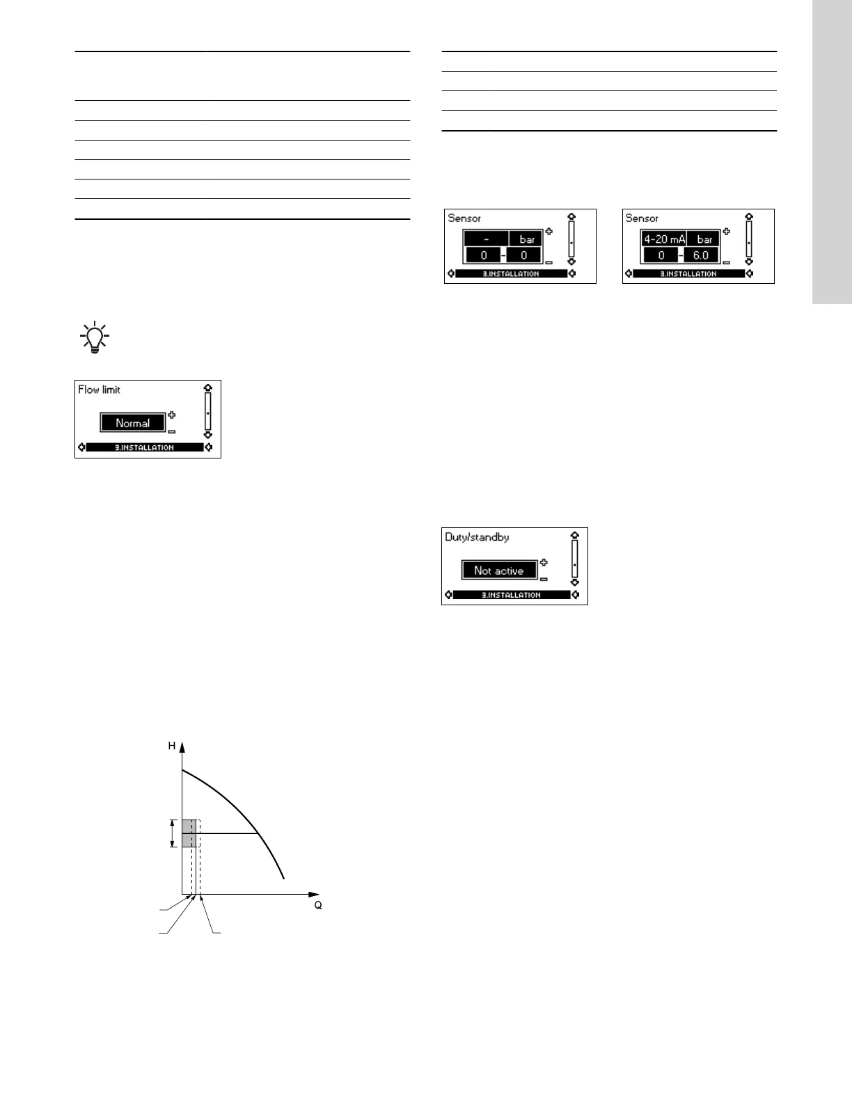
5.4.10 Sensor
Without sensor
(uncontrolled)
With pressure sensor
(controlled)
HM_M3P16_1
HM_M3P16_2
The setting of the sensor is only relevant in the case of controlled
operation.
Select among the following values:
• Sensor output signal
0-10 V
0-20 mA
4-20 mA.
•
Unit of measurement of sensor: bar, mbar, m, kPa, psi, ft, m
3
/h,
m
3
/s, l/s, gpm, °C, °F, %,
• Sensor measuring range.
5.4.11
Duty/standby
The duty/standby function applies to two pumps connected in
parallel and controlled via GENIbus.
The duty/standby function can be set to these values:
• Active
• Not active.
When the function is set to Active, the following applies:
• Only one pump is running at a time.
• The stopped pump (standby) will automatically be cut in if the
running pump (duty) has a fault. A fault will be indicated.
• Changeover between the duty pump and the standby pump will
take place every 24 hours.
Activate the duty/standby function as follows:
1. Install and prime the two pumps according to the installation and
operating instructions supplied with the pumps.
2. Check that the power supply is connected to the first pump
according to the installation and operating instructions.
3. Use Grundfos R100 to set the duty/standby to Not active in the
installation menu.
4. Use Grundfos R100 to set the Operating mode to Stop in the
operation menu.
5. Use Grundfos R100 to set the other displays as required for the
pump application (such as setpoint).
6. Disconnect the power supply to both pumps.
19
English (US)

 Loading...


