11
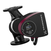
MAGNA3 INSULATED PUMPS INSTALLATION MANUAL
Plumbing
Unit Plumbing
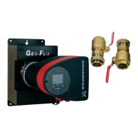
There are several water valve options available to regulate flow to the heat pumps.
A. WWKVS – is designed for use with variable speed units, and dual capacity units with AXB controls. When using this kit you will
need to use the AID tool to adjust minimum and maximum flow rates. The factory default is minimum = 50% and maximum =
100% flow rate for variable speed units, and minimum = 75% and maximum = 100% for dual capacity units. Refer to the units
Installation manual under unit Start Up for more information on setting up through the AID tool. Always ensure that there is
adequate flow for the heat pump. Refer to the units Specification Manual for minimum and maximum flow rates. NOTE: the
10DC must be attached to screw position 1 on the VS labeled section of the AXB. See figure 10 for wiring schematic.
Figure 10: Modulating Water Valve Connection
B. WWK3T – is designed for dual capacity units without the AXB controls. This kit uses solenoid valve, slow closing valve, and ball
valves to regulate flow for both high and low speed operation. Always ensure that there is adequate flow for the heat pump. Refer to
units Specification Manual for minimum and maximum flow rates. See figure 11 and 12 for wiring schematic.
Factory
Fault
ALG
ALM
LS
ES
ACC c
Status
Aurora
Base Control
RV – K1
CC2
CC – K2
CC Hi – K3
Fan – K4
Alarm – K5
Acc – K6
ACC no
ACC nc
O/B
C
R
LO
G
Y1
Y2
W
DH
3A-F use
O/B
C
R
LO
G
Y1
Y2
W
DH
LO
G
HI
CCG
CC
FG
F
R
HP
HP
LP
FP2
FP2
FP1
REV
REV
CFM
PWM
ECM PWM
Factory
Factory Fan Connection
RR
CC
C
C
R
A
B
RS 485
EH2
C
EH1
C
CO
B
A
R
C
RS 485 E xp
Factory
Com1
Com2
Config
G
G
G
YR
SW1 Test
FP1 – 15
o
F/30
o
F
JW2 - Alarm
P11
P5
P2
P1
P8
P7
P9
P6
P3
SW2
P13
P4
FP 2 – 15
o
F/30
o
F
RV – B/O
ACC – Dip 1
ACC – Dip 2
CC – Dual/Single
L – Pulse/Continuous
Reheat/Normal
Factory Use
Field ConnectionsField Connections
C
LP
FP1
F
CC
G
Y1
1
2
3
4
5
6
7
8
Off
On
N/A
RS 485 NE T
CC
Taco Valve
V100FPT
C
W/Y
CC2
SV
Figure 11: Aurora Dual-Capacity with Communicating or Non-
Communicating Thermostat (ABC Only)
Figure 12: Wiring diagram for dual water valve installation
VS PUMP
GND
24 VAC
0-10DC
1
2
3
R
C
ABC BOARD
AXB BOARD
2 1
VALVE
(23P529-01)
C
W/Y
CCG or CC GND
CC
CC
U
SV
CC2 or CCHI
Logic Board
Taco Valve
V100FPT
(Type V)
BPV/PPV
Solenoid
Compressor
Contactor
Coil
Heat Pump
Control Board

 Loading...


