English (GB)
7
6. Installation
6.1 Location
Observe the following to ensure adequate cooling of motor and
electronics:
• Position Hydro Multi-E in such a way that adequate cooling is
ensured. See section 6.2.1 Ensuring motor cooling
• The ambient temperature must not exceed 50 °C.
• Keep motor cooling fins and fan blades clean.
The booster system must have a 1-metre clearance in front and
on the two sides.
6.2 Mechanical installation
Arrows on the pump base show the direction of the flow of water
through the pump.
1. The pipes connected to the booster system must be of
adequate size. Fit expansion joints in the inlet and outlet pipes
to avoid resonance. See fig. 8.
Connect the pipes to the manifolds of the booster system.
The manifold comes with a screw cap fitted to one end. If this end
is to be used, remove the screw cap, apply sealing compound to
the other end of the manifold, and fit the screw. Fit a blanking
flange with gasket on flanged manifolds.
Tighten up the booster system before starting it.
If booster systems are installed in blocks of flats or the first
consumer on the line is close to the booster system, we
recommend that you fit expansion joints on the inlet and outlet
pipes to prevent vibration being transmitted through the pipes.
See fig. 8.
2. Position the booster system on a plane and solid surface, for
example a concrete floor or foundation. If the booster system
is not fitted with vibration dampers, it must be bolted to the
floor or the foundation.
3. Fasten the pipes to parts of the building to ensure that they
cannot move or be twisted.
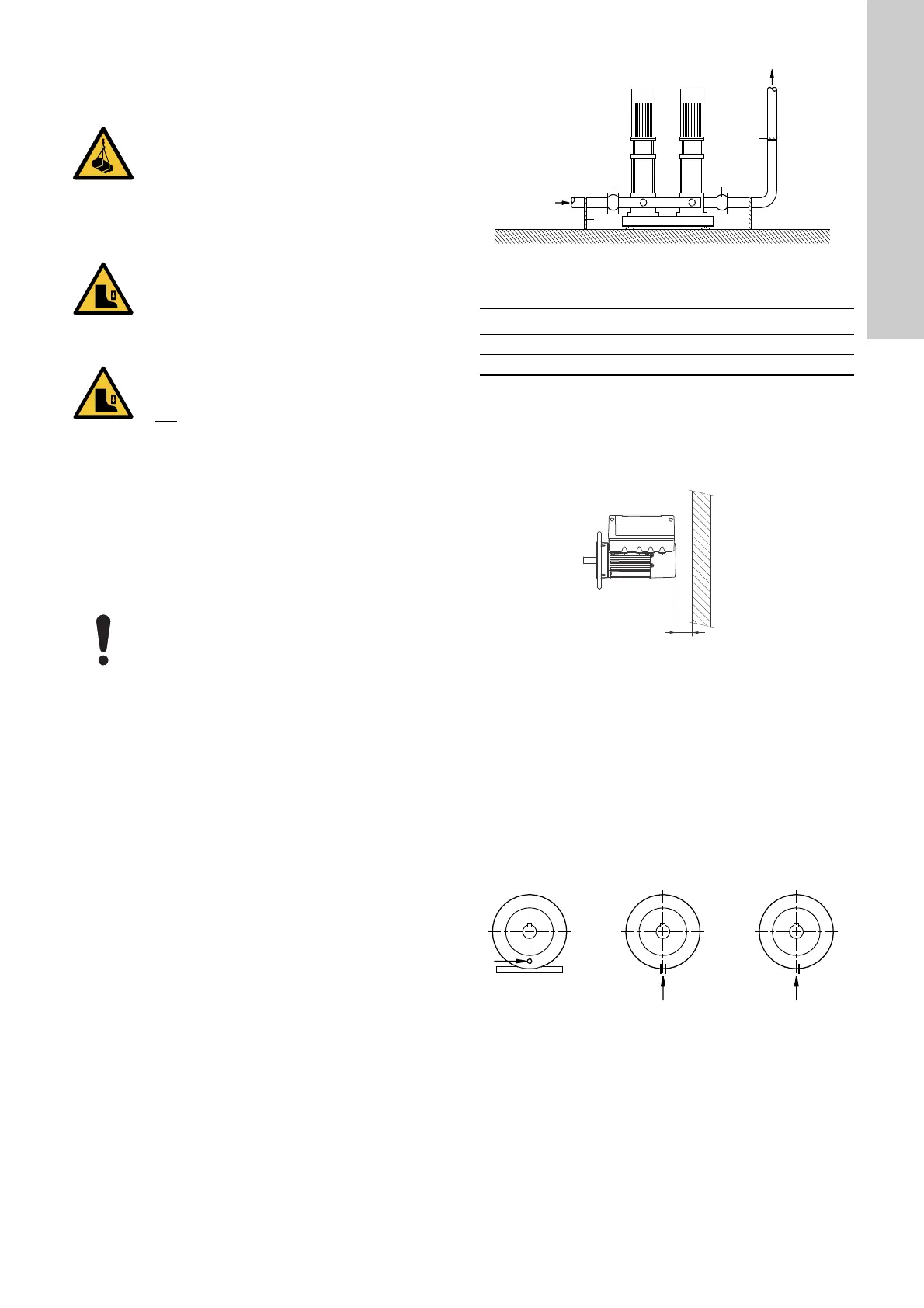
Fig. 8 Installation example with expansion joints and pipe
supports
The expansion joints and pipe supports shown in fig. 8 are not
included in the standard booster system.
6.2.1 Ensuring motor cooling
Leave at least 50 mm between the end of the fan cover and a wall
or other fixed objects. See fig. 9.
Fig. 9 Minimum distance (D) from the motor to a wall or other
fixed objects
6.3 Drain holes
When the motor is installed in moist surroundings or areas with
high humidity, the bottom drain hole must be open. If the humidity
is constantly high and above 85 %, open the drain holes in the
drive-end flange. The enclosure class of the motor will then be
lower. This helps prevent condensation in the motor as the motor
becomes self-venting, and it allows water and humid air to
escape.
The motor has a plugged drain hole on the drive side. You can
turn the flange 90 ° to both sides or 180 °.
Fig. 10 Drain holes
WARNING
Overhead load
Death or serious personal injury
- Use safety equipment when mounting the base
frame.
- Restrict access to area.
- Installation must be carried out by trained
personnel.
WARNING
Crushing of feet
Death or serious personal injury
- Use safety equipment when replacing the flange.
- Restrict access to area.
- Installation must be carried out by trained
personnel.
CAUTION
Crushing of feet
Minor or moderate personal injury
-Use
safety equipment when installing the tank.
For outdoor installation, always place the system
under a roof to avoid exposing the system to direct
sunlight. See section 28. Inputs and outputs
TM00 7748 1996
Pos. Description
1 Expansion joint
2 Pipe supports
TM05 5236 3512
TM02 9037 1604