English (GB)
41
27.2
Installation altitude
Installation altitude is the height above sea level of the installation
site. Motors installed up to 1000 m above sea level can be loaded
100 %. The motors can be installed up to 3500 m above sea
level.
Fig. 60 Motor output power in relation to altitude
In order to maintain the galvanic isolation and ensure correct
clearance according to EN 60664-1:2007, you must adapt the
supply voltage to the altitude:
Fig. 61 Motor output power in relation to altitude
In order to maintain the galvanic isolation and ensure correct
clearance according to EN 60664-1:2007, you must adapt the
supply voltage to the altitude:
Fig. 62 Supply voltage for three-phase motor in relation to
altitude
Supply voltage for single-phase motor in relation to altitude
27.3 Humidity
Maximum 95 %.
27.4 Maximum operating pressure
See system nameplate.
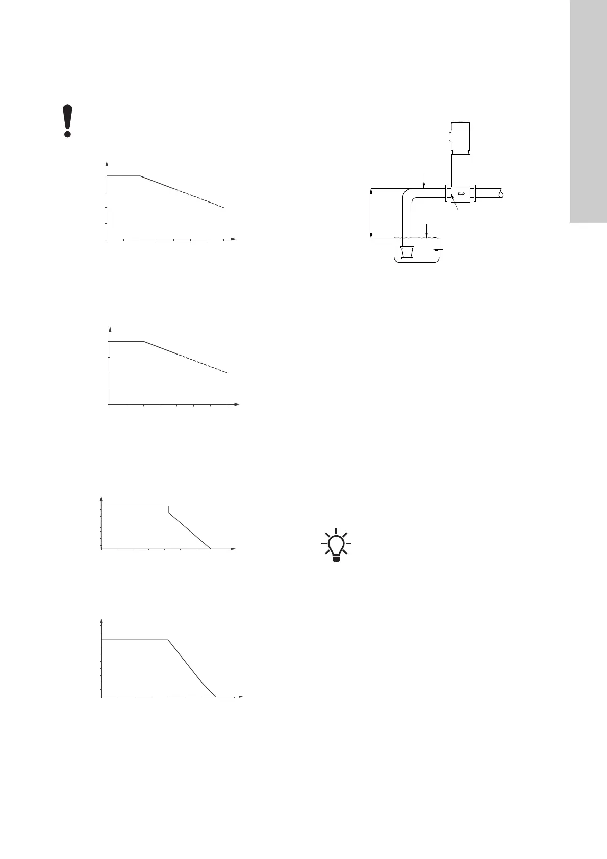
27.5 Minimum inlet pressure
Fig. 63 Parameters for the calculation of minimum inlet
pressure
The minimum inlet pressure "H" in metres head required to avoid
cavitation in the pumps can be calculated as follows:
Motors installed more than 1000 m above sea level
must not be fully loaded due to the low density and
consequent low cooling effect of the air.
TM05 5243 3717
TM05 5243 3717
TM06 9866 3617
TM06 9867 3617
0
500 1000 1500 2000 2500 3000 3500
0
60
80
90
70
100
500 1000 1500 2000 2500 3000 3500
500 2500 35001500
500
480
460
440
420
380
400
Y
X
Supply voltage [V]
Altitude [m]
0 500 1000 1500 2000 2500 3000 3500 4000
200
210
220
230
240
250
Supply voltage [V]
Altitude [m]
TM02 0118 3800
H = pb x 10.2 - NPSH - Hf - Hv - Hs
pb = Barometric pressure in bar. Barometric pressure can
be set to 1 bar.
In closed systems, p
b
indicates the system pressure
in bar.
NPSH = Net Positive Suction Head in metres head
The NPSH value can be read from the NPSH curve at
the highest flow which the individual pump will be
delivering.
Hf = Friction loss in inlet manifold in metres head at the
highest flow the individual pump will be delivering.
Note: If a non-return valve is installed on the inlet
side of the pump, the friction loss in the valve must be
added. See the manufacturer's data.
Hv = Vapour pressure in metres head.
Hs = Safety margin of min. 0.5 metres head.
In some regions, the booster system is available with
a low inlet manifold which makes it more suitable for
suction lift operation. Contact Grundfos for further
information.