English (GB)
2
English (GB) Installation and operating instructions
Original installation and operating instructions
These installation and operation instructions apply to the
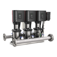
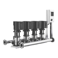
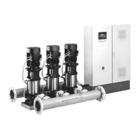
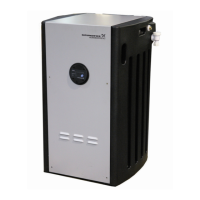
Grundfos Hydro Multi-E booster systems.
CONTENTS
Page
1. Symbols used in this document
3
1.1 Warnings against hazards involving risk of death or
personal injury
3
1.2 Other important notes
3
2. Product introduction
3
2.1 Product description
3
2.2 Intended use
3
3. Receiving the product
4
3.1 Transporting the product
4
3.2 Inspecting the product
4
3.3 Scope of delivery
4
3.4 Handling and lifting the product
4
4. Identification
5
4.1 Nameplate
5
5. Type key
6
6. Installation
7
6.1 Location
7
6.2 Mechanical installation
7
6.3 Drain holes
7
6.4 Electrical installation
8
6.5 Mains supply
8
6.6 Additional protection
9
6.7 Connection terminals
9
6.8 Signal cables
13
7. Optional bus communication via Grundfos CIM
modules
13
7.1 Installing a Communication Interface Module
13
8. Identification of functional module
14
9. Startup
15
9.1 Hygiene
15
9.2 Hydro Multi-E in system with positive inlet pressure
15
9.3 Hydro Multi-E in system without inlet pressure
16
10. User interfaces
16
10.1 Standard control panel
16
10.2 Advanced control panel
18
11. Multimaster function
19
11.1 Systems with two or more outlet-pressure sensors
19
12. Description of functions for the system
19
12.1 Settings
19
12.2 Operating mode
19
12.3 Control mode
20
12.4 Pipe-filling function
20
12.5 Stop function
21
12.6 Controller
22
12.7 Operating range
23
12.8 Limit-exceeded function
23
12.9 Proportional pressure
24
12.10 "Pump changeover"
24
12.11 "Undo"
24
12.12 "Pump name"
24
12.13 "Unit configuration"
24
13. Description of functions for pumps
25
13.1 Analog inputs
25
13.2 Pt100/1000 inputs
26
13.3 Digital inputs
26
13.4 Digital inputs/outputs
27
13.5 "Signal relays" 1 and 2 ("Relay outputs")
28
13.6 "Analog output"
28
13.7 External setpoint function
29
13.8 "Predefined setpoints"
30
13.9 Alarm log
30
13.10 Warning log
30
13.11 "Multi-pump setup"
30
14. Setting the product (E products)
31
14.1 Setting by means of the pumps
31
14.2 Setting by means of Grundfos GO Remote
31
14.3 Communication
31
14.4 Menu overview for Grundfos GO Remote
32
15. Protective functions
33
15.1 Dry-running protection
33
16. Priority of settings
35
17. Grundfos Eye
36
18. Signal relays
37
19. Digital input
38
20. Data communication
38
21. Maintenance
38
21.1 Pumps
38
21.2 Motors
38
21.3 Breaker cabinet
38
21.4 Service kits
38
22. Taking the product out of operation
38
22.1 Frost protection
38
23. Startup the product after standstill
38
24. Fault finding
39
25. Technical data, Hydro Multi-E with single-phase
pumps
40
25.1 Supply voltage
40
25.2 Leakage current
40
25.3 Torques
40
26. Technical data, Hydro Multi-E with three-phase
pumps
40
26.1 Supply voltage
40
26.2 Leakage current
40
26.3 Torques
40
27. Operating conditions
40
27.1 Temperatures
40
27.2 Installation altitude
41
27.3 Humidity
41
27.4 Maximum operating pressure
41
27.5 Minimum inlet pressure
41
27.6 Maximum inlet pressure
42
27.7 Minimum flow rate
42
27.8 Maximum starts and stops
42
27.9 Diaphragm tank
42
28. Inputs and outputs
42
29. Factory settings
44
30. Other technical data
45
31. Sound pressure level
45
31.1 Hydro Multi-E with single-phase pumps
45
31.2 Hydro Multi-E with three-phase pumps
45
32. Disposal
45
Read this document before installing the product.
Installation and operation must comply with local
regulations and accepted codes of good practice.
 Loading...
