If the inflow of liquid exceeds the capacity of the installed pump, the
level in the tank or well starts to rise. Eventually, the High level
sensor registers a high liquid level in the tank or well. If set, the
signal from the High level sensor can be used to activate an output
relay which can then be used to give a visual or acoustic alarm or
send a signal to a SCADA system.
If the pump is running and the liquid level in the tank or well falls
below the dry-running level, the dry-running protection stops the
pump to ensure that it is not damaged mechanically.
Fill
TM075205
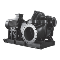
Pos. Description
1 High level
2 Stop level
3 Start level P1: start level for pump 1
4 Not in use
5 Dry-running level
In the filling application, the pump is installed in a tank or well from
where it pumps the liquid. The liquid is pumped into a second tank
where the level sensors are installed.
The pump starts to fill the second tank when Start level P1 is
reached.
The pump stops when the liquid level reaches Stop level.
If the pump for some reason does not stop at Stop level and the
liquid level keeps rising, the High level sensor eventually
registers this. If set, the signal from the High level sensor can be
used to activate a relay output which can then be used to give a
visual or acoustic alarm or send a signal to a SCADA system via a
communication interface.
If the pump is running and the liquid level in the tank falls below the
dry-running level, the dry-running protection stops the pump to
ensure that it is not damaged.
Related information
6.14.1 Automatic operation
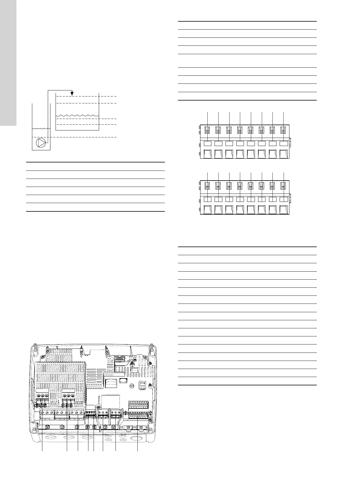
4.5 Terminals
TM070123
Pos. Description
1 Contactor for pump 1
2 Not in use
3 Terminal block for the power supply
4
Terminal block for temperature and moisture-protection
sensor for pump 1
5 Not in use
6 Alarm 1
7 Alarm 2
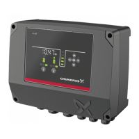
8 Analog and digital inputs and outputs.
DIO1
GND DIO2 GND
DI1
GND
DI2 GND
CIO1
GND
CIO2 GND
24V GND 24V
GND
1 2
3
4
5
6 7
8
9 10 11 12 13 14 15 16
TM070124
Connect to Grundfos GO Remote to see which options are
available for the input and output terminals.
Pos.
Description
1 Digital input/output 1, configurable
2 GND
3 Digital input/output 2, configurable
4 GND
5 Digital input 1
6 GND
7 Digital input 2
8 GND
9 Configurable input/output 1
10 GND
11 Configurable input/output 2
12 GND
13 Supply voltage, 24 V, max. 200 mA
14 GND
15 Supply voltage, 24 V, max. 200 mA
16 GND
Related information
3.6 Configuring the IO terminals using Grundfos GO Remote
12
English (GB)
 Loading...