1. Loosen the screws.
2. Carefully separate the front cover from the back cover.
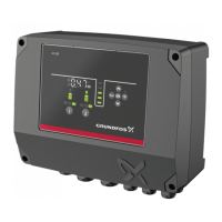
3. Pull out the flat cable that is connected to the circuit board. Do
not remove the flat cable from the front cover.
TM071323
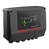
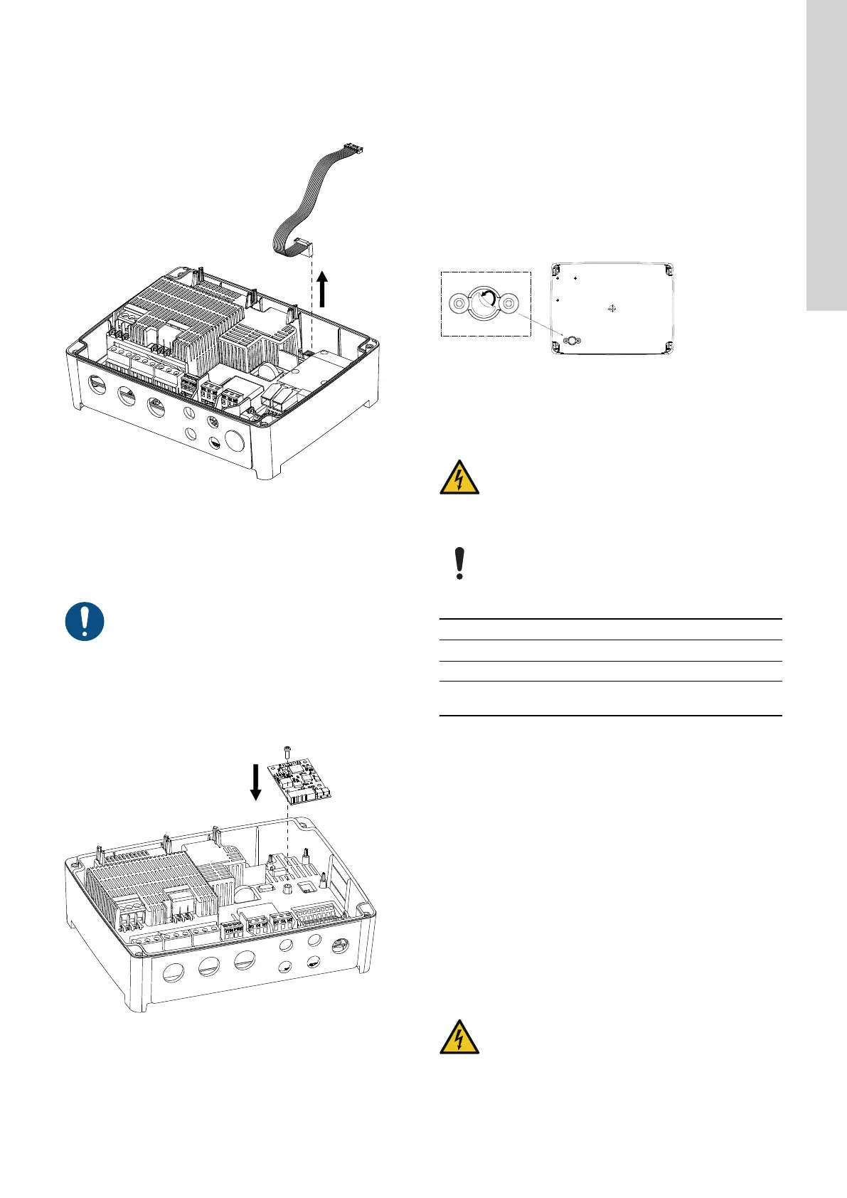
2.2.5 Installing a communication interface module
You can fit a communication interface module (CIM) in the control
unit to enable communication with external systems. The module is
optional and is not delivered with the product. See the installation
and operating instruction for the module regarding electrical
connections.
Use an antistatic service kit when handling electronic
components. This prevents static electricity from
damaging the components.
1. Loosen the screws and remove the front cover.
Be careful not to damage the cable between the front cover and
the back cover.
2. Push the module onto the three guide pins and into the socket.
Press the module home, using your fingers.
TM070130
3. Fit the screw to lock the module.
4. Place the labels supplied with the module on the back of the
front cover.
5. Make the electrical connections to the module as described in
the instructions supplied with the module.
6. Route the wires for the module through one of the cable glands.
For modules with LAN or antenna cables, you must order an
additional cable gland M20.
7. Fit the cover and cross-tighten the mounting screws.
Related information
2.2.3 Removing the front cover
4.7 Supported communication interface modules and protocols
8.19 Code 159 (Communication error CIMxxx)
2.2.6 Removing the membrane
For applications where drainage is required, the membrane must be
removed.
1. Pull the membrane off the back of the control unit.
TM074551
2.3 Electrical connection
2.3.1 Cable requirements
WARNING
Electric shock
Death or serious personal injury
‐ The wires from the pump phases must be rated at 90
°C (194 °F).
‐ The wires from the temperature sensor, if any, must be
rated at 480 V and 70 °C (158 °F).
Changes or modifications not expressly approved by
Grundfos may void the user's authority to operate the
equipment.
Cable cross-sections
Type of cable
Stranded with ferrule Solid
Cross-section
[mm
2
]
[AWG]
[mm
2
]
[AWG]
Contactor for the pump 1.5 - 2.5 16-14 1.5 - 4 16-12
Terminal block for the
power supply
2.5 - 10 14-8 2.5 - 16 14-6
2.3.2 Protection of controller and supply cables
The controller and power cables must be protected against short-
circuits and overloads. The protection must be accomplished using
components such as:
• fuse of melt type gL and gG
• fuse type gD
• circuit breaker of type C.
See the rated current for this specific product on the product
nameplate.
Related information
9.2 Mechanical data
2.3.3
Connecting the pump supply and power supply
Pumps may be equipped with PTC/Klixon sensors (thermal
switched) which protect against overheating.
Some also have moisture sensors indicating water in the pump.
DANGER
Electric shock
Death or serious personal injury
‐ In case of an insulation fault, the fault current may be
a pulsating DC. Observe national legislation about
requirements for and selection of Residual Current
Device (RCD) when installing the product.
7
English (GB)
 Loading...