WARNING
Electric shock
Death or serious personal injury
‐ Switch off the power supply before making any
electrical connections.Make sure that the power
supply cannot be switched on accidentally.
‐ Remember to indicate where the main switch is
located by placing a label or similar marking on the
control unit.
‐ Make sure that the voltage between the phase and
neutral does not exceed 250 VAC.
‐ Electrical connections must be carried out according to
the wiring diagrams.
Do not add additional components other than those
illustrated on the wiring diagram. Do not use unused pin
holes for other connections.
All cable glands and plugs must be mounted after the
installation is completed.
If the gaskets are not pre-mounted on the cable glands,
mount them on the cable glands before the control unit is
mounted on the wall.
For the PTC connection, do not connect the third wire
(common wire) in the control unit. It must be isolated with
a cable-end cap.
Take into account the total leakage current of all the electrical
equipment in the installation.
1. Check that the supply voltage and frequency correspond to the
values stated on the nameplate.
2. Cut the power supply and pump cables as short as possible.
3. Before switching the power on, check all voltages with a
multimeter and make sure that the voltage between neutral and
each phase does not exceed 250 VAC.
4. Connect the power cables and pump cables according to the
relevant electrical diagram, including the cables from the motor
temperature and moisture sensor, if any. Tighten the terminal
screws to the correct torque. See the table below.
• All wires must be secured inside the cabinet using
cable ties.
• The wires must not cross the safety barriers
between the connectors.
• All cable glands must be mounted and
plugged, even if they are not in use, to ensure the
correct IP protection level.
Remember to remove the jumper from the PTC terminal if you
are connecting cables from the temperature sensor to the PTC
terminals.
Terminal block
Torque [Nm]
Pump contactor 1.2 - 1.5
Power supply 1.2 - 1.5
Cable glands 2.5
TM070570
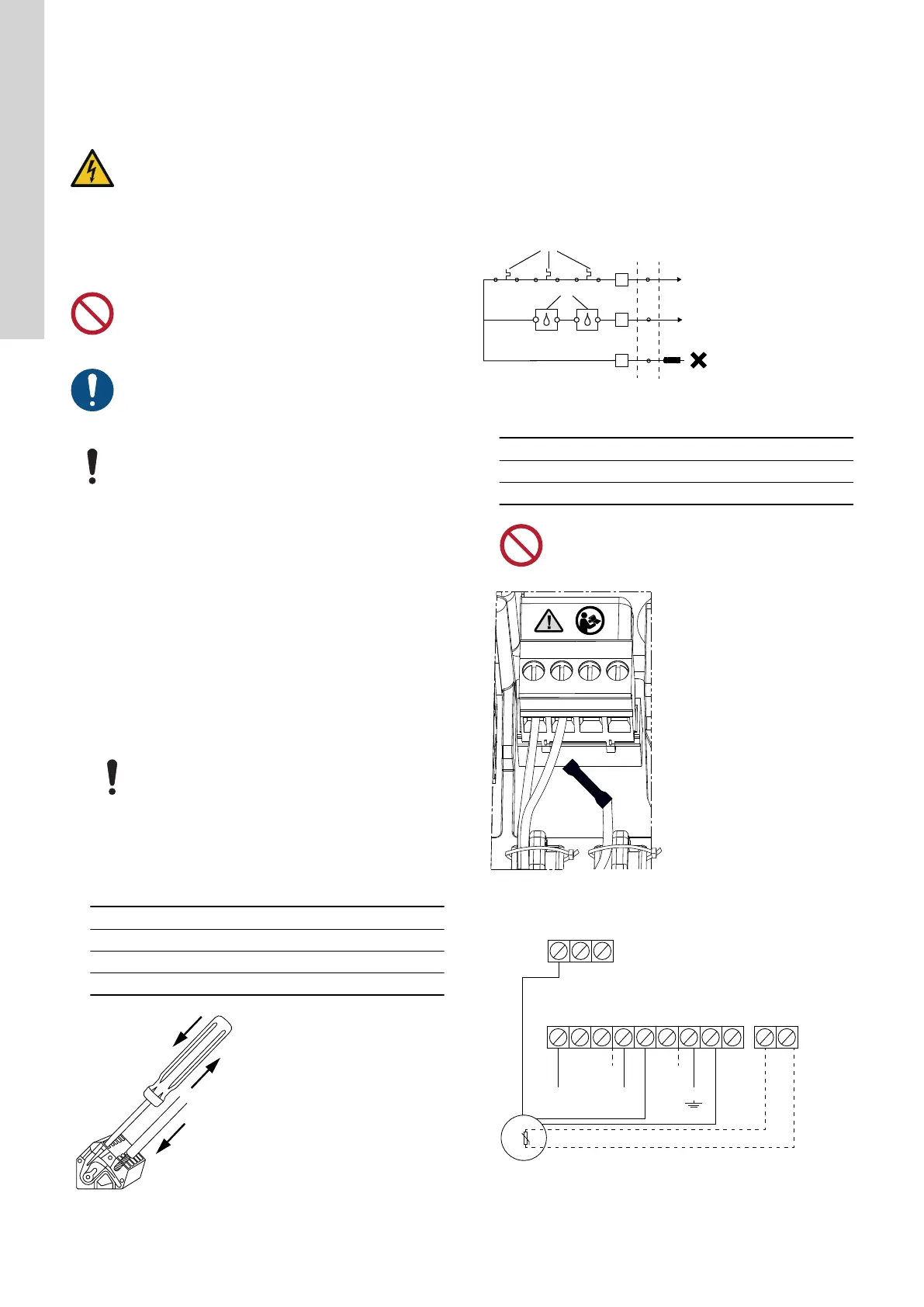
Connecting a wire to a terminal with spring clamps
5. In case there is only a PTC sensor present in the pump, the two
wires from the PTC sensor have to be connected directly to the
PTC terminals.
6. In cases where PTC and moisture sensors are present, you end
up with three wires: a PTC wire, a moisture sensor wire and a
common wire. Connect only the PTC wire and the moisture
sensor wire. The common wire must be isolated.In Grundfos GO
Remote, you must select that both the PTC wire and
the moisture sensor wire are connected, and select a cool-down
time for the thermal protection.
TM076634
PTC connection
Pos. Description
1 PTC/Klixon sensors
2 Moisture sensors
Do not connect Pt100/1000 sensors to the PTC
terminals. You must use CIO1 or CIO2 for Pt100/1000
sensors.
Recommended PTC wiring
Example:
L2 L3L1
L
N PE
N
NN BA
PE
PE
PE
PTC1
T2 T3T1
M
TM070127
Single-phase connections for one pump
8
English (GB)
 Loading...