L2 L3L1
PE
N
NN
L2 L3
L1 N
EARTH
B
A
B
A
PE PTC1
PTC2
T2
T3T1
M1
TM074093
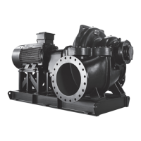
Three-phase connections for one pump
L2 L3L1
PE
N
N
L2 L3
L1
B
A
B
A
PE
PE
PE
PTC1
PTC2
T2
T3T1
M1
TM074094
Three-phase connections for one pump without neutral, for Norway
only
Related information
2.2.1 Mounting the rubber seals
6.15.4 Setting the motor protection with Grundfos GO Remote
8.2 Code 2 (Power phase missing)
8.4 Code 9 (Power phase sequence wrong)
8.21 Code 181 (Signal fault, PTC input)
2.3.4
Connecting a level sensor
You can either connect an analog level sensor, such as a pressure
sensor, or digital level sensors, such as float switches.
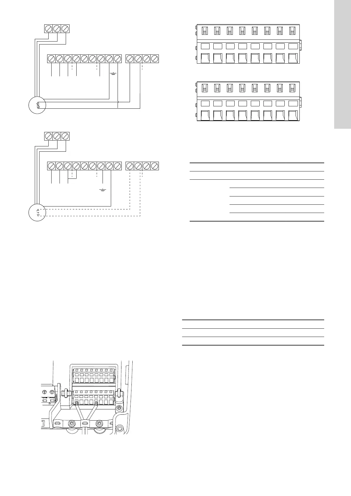
1. Loosen the screws and remove the front cover.
Be careful not to damage the cable between the front cover and
the back cover.
2. Lead the wires through one of the cable glands.
3. Depending on the type of wire, take one of the following actions:
• For a shielded wire, lead it through the cable clamp.
TM070571
• For a not shielded wire, attach it to the protection cover with a
cable tie.
DIO1
GND DIO2
GND
DI1
GND
DI2
GND
CIO1
GND
CIO2 GND
24V
GND
24V
GND
TM070760
4. Depending on the type and function of the sensor, connect the
wires to the following terminals. When using an analog sensor,
level switches can be used to add redundance or security by
adding an extra dry-running sensor or high-level sensor or both.
Sensor type Sensor function Terminals
Analog All levels CIO1 - 24 V
Digital
Dry-running level CIO2 - GND
Stop level DIO1 - GND
Start level, pump 1 DIO2 - GND
Not in use DI1 - GND
High level DI2 - GND
Related information
2.2.3 Removing the front cover
2.3.5
Connecting an alarm device
You can connect an alarm device, such as a buzzer or a lamp, to
the output relays Alarm 1 and Alarm 2. The control unit triggers the
alarm device when it detects an alarm or a warning. You can
change the behaviour of the outputs with Grundfos GO Remote
under Relay output 1 and Relay output 2.
You can also set the alarm device to be activated during normal
operation. It will only be deactivated in case of an alarm, a
warning or mains failure. The setting is made in Grundfos GO
Remote.
Go to Settings > LC 232 IO terminals > Relay output > Function.
Default settings of the terminal blocks
Terminal block
Default function
Alarm 1 All alarms
Alarm 2 High level
1. Loosen the screws and remove the front cover.
Be careful not to damage the cable between the front cover and
the back cover.
2. Lead the wires through one of the cable glands.
3. Depending on the type of the alarm device, connect the wires to
the relevant terminals. Note that all wires must be secured
inside the cabinet using cable ties.
• NO (Normally Open) and C (Common)
• NC (Normally Closed) and C (Common).
9
English (GB)
 Loading...