Observe these instructions for explosion-proof products.
A blue or grey circle with a white graphical symbol
indicates that an action must be taken.
A red or grey circle with a diagonal bar, possibly with a
black graphical symbol, indicates that an action must not
be taken or must be stopped.
If these instructions are not observed, it may result in
malfunction or damage to the equipment.
Tips and advice that make the work easier.
2. Installing the product
2.1 Location
Install the product in a location that meets the following
requirements:
• Place the product in a flood-safe place.
• Make sure that the ambient temperature is within the limits.
• Install the product as close as possible to the connected pumps,
sensors, and accessories.
• The product must be protected from direct sunlight.
• The product must be easily accessible.
• Indoor installation: The product must be installed in a well-
ventilated room to ensure cooling of its components.
2.2 Mechanical installation
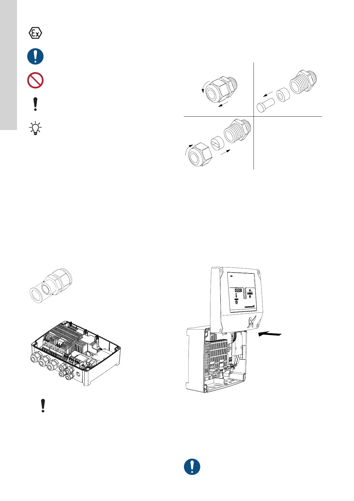
2.2.1 Mounting the rubber seals
1. Mount the supplied rubber seals on the cable glands.
TM074473
2. Mount the cable glands on the control unit.
TM074474
Do not tighten the cable glands too much since this
may damage the rubber seals.
Related information
2.3.3 Connecting the pump supply and power supply
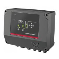
2.2.2
Mounting the rubber insert
If you are using oval cables, you need to replace the rubber insert
to ensure proper closure.
1. Remove the outer part of the cable gland (pos. 1).
2. Remove the rubber plug and rubber insert from the cable gland
(pos. 2).
3. Place the new oval insert inside the cable gland and refit the
outer part (pos. 3).
Example:
TM077964
2.2.3 Removing the front cover
Place the front cover above the control unit, if possible. This
way, you do not need to remove the flat cable between the front
cover and the control unit.
1. Loosen the screws.
2. Carefully separate the front cover from the back cover.
Be careful not to damage the cable connecting the front cover
and the back cover.
3. Place the front cover above the back cover on the support
brackets.
4. To ensure that the front cover does not tilt, insert the two bottom
screws into the open holes at the top of the back cover.
TM077202
Related information
2.2.5 Installing a communication interface module
2.3.4 Connecting a level sensor
3.6 Configuring the IO terminals using Grundfos GO Remote
2.2.4
Disconnecting the front cover
If you need to remove the front cover completely, you must remove
the flat cable between the front cover and the back cover.
Use an antistatic service kit when handling electronic
components. This prevents static electricity from
damaging the components.
6
English (GB)
 Loading...