English (GB)
5
3.3 Mechanical installation
The pump range includes both flanged and threaded versions.
These installation and operating instructions apply to both
versions, but give a general description of flanged versions. If the
versions differ, the threaded version will be described separately.
Install the pump so that it is not stressed by the pipes. For
maximum permissible forces and moments from pipe connections
acting on the pump flanges or threaded connections, see page
26.
You can suspend the pump directly in the pipes, provided that the
pipes support the pump.
Twin-head pumps are prepared for installation on a mounting
bracket or base plate. Pump housing with M12 thread.
To ensure adequate cooling of motor and electronics, observe the
following requirements:
• Position the pump in such a way that sufficient cooling is
ensured.
• The ambient temperature must not exceed 40 °C.
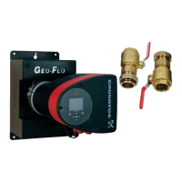
3.3.1 Pump positions
Always install the pump with horizontal motor shaft.
• Pump installed correctly in a vertical pipe. See fig. 8, pos. A.
• Pump installed correctly in a horizontal pipe.
See fig. 8, pos. B.
• Do not install the pump with vertical motor shaft.
See fig. 8, pos. C and D.
Fig. 8 Pump installed with horizontal motor shaft
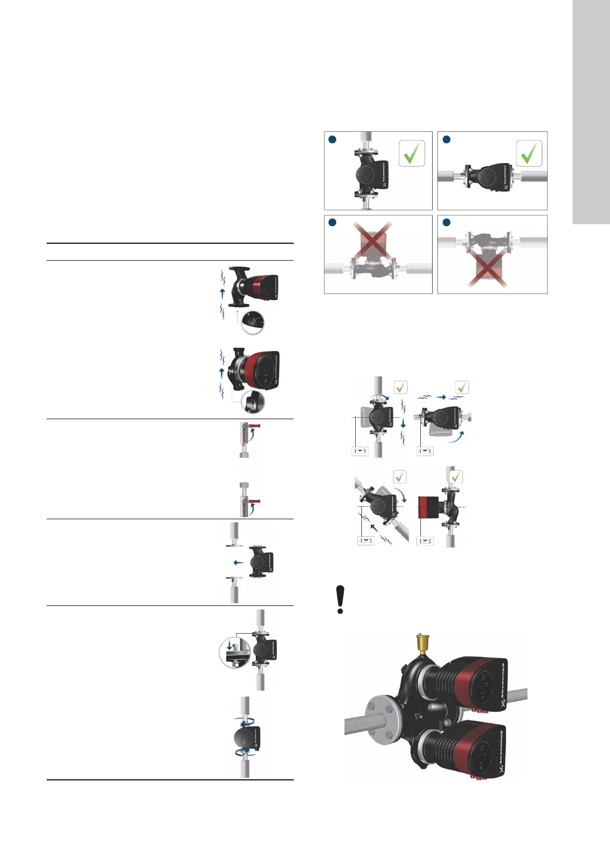
3.3.2 Control box positions
To ensure adequate cooling, make sure that the control box is in
horizontal position with the Grundfos logo in vertical position. See
fig. 9.
Fig. 9 Pump with control box in horizontal position
Fig. 10 Automatic vent
Step Action Illustration
1
Arrows on the pump housing
indicate the liquid flow direction
through the pump. The liquid flow
direction can be horizontal or
vertical, depending on the
control-box position.
TM05 5513 3812TM05 5514 3812
2
Close the isolating valves and
make sure that the system is not
pressurised during installation of
the pump.
TM05 2863 0612
3
Mount the pump with gaskets in
the pipes.
TM05 5515 3812
4
Flanged version:
Fit the bolts, washers and nuts.
Use the correct size of bolts
according to system pressure.
For further information about
torques, see page 26.
Threaded version:
Tighten the union nuts.
TM05 5516 3816 TM05 5517 3812
TM05 5518 3016TM05 5522 3016
Fit twin-head pumps installed in horizontal pipes
with an automatic air vent, Rp 1/4, in the upper part
of the pump housing. See fig. 10.
TM05 6062 3016
 Loading...