English (GB)
15
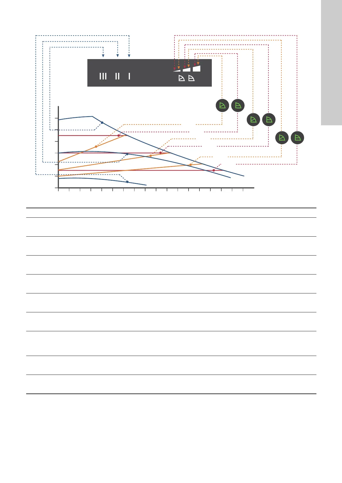
7.1 Overview of control functions
Fig. 26 Pump setting in relation to pump performance
TM05 2777 0512
Setting Pump curve Function
PP1
Lowest proportional-pressure
curve
The duty point of the pump will move up or down on the lowest proportional-pressure curve,
depending on the heat demand. See fig. 26.
The head is reduced at falling heat demand and increased at rising heat demand.
PP2
Intermediate
proportional-pressure curve
The duty point of the pump will move up or down on the intermediate proportional-pressure
curve, depending on the heat demand. See fig. 26.
The head is reduced at falling heat demand and increased at rising heat demand.
PP3
Highest
proportional-pressure curve
The duty point of the pump will move up or down on the highest proportional-pressure curve,
depending on the heat demand. See fig. 26.
The head is reduced at falling heat demand and increased at rising heat demand.
CP1
Lowest constant-pressure
curve
The duty point of the pump will move out or in on the lowest constant-pressure curve,
depending on the heat demand in the system. See fig. 26.
The head is kept constant, irrespective of the heat demand.
CP2
Intermediate
constant-pressure curve
The duty point of the pump will move out or in on the intermediate constant-pressure curve,
depending on the heat demand in the system. See fig. 26.
The head is kept constant, irrespective of the heat demand.
CP3
Highest constant-pressure
curve
The duty point of the pump will move out or in on the highest constant-pressure curve,
depending on the heat demand in the system. See fig. 26.
The head is kept constant, irrespective of the heat demand.
III Speed III
The pump runs on a constant curve which means that it runs at a constant speed.
At speed III, the pump is set to run on the maximum curve under all operating conditions.
See fig. 26.
You obtain quick venting of the pump by setting the pump to speed III for a short period.
II Speed II
The pump runs on a constant curve which means that it runs at a constant speed.
At speed II, the pump is set to run on the intermediate curve under all operating conditions.
See fig. 26.
I Speed I
The pump runs on a constant curve which means that it runs at a constant speed.
At speed I, the pump is set to run on the minimum curve under all operating conditions. See
fig. 26.
III
II
I
H
PP3
CP3
CP2
PP1
CP1
PP2
Q

 Loading...


