English (GB)
8
3.4 Electrical installation
Carry out the electrical connection and protection according to
local regulations.
Check that the supply voltage and frequency correspond to the
values stated on the nameplate.
• Make sure that the pump is connected to an external main
switch.
• The pump requires no external motor protection.
• The motor incorporates thermal protection against slow
overloading and blocking.
• When switched on via the power supply, the pump starts after
approximately 5 seconds.
3.4.1 Supply voltage
1 x 230 V ± 10 %, 50/60 Hz, PE.
The voltage tolerances are intended for mains-voltage variations.
Do not use the voltage tolerances for running pumps at other
voltages than those stated on the nameplate.
3.4.2 Connection to the power supply
Terminal-connected versions
WARNING
Electric shock
Death or serious personal injury
- Lock the main switch in position 0. Type and
requirements as specified in EN 60204-1, 5.3.2.
WARNING
Electric shock
Death or serious personal injury
- Connect the pump to an external main switch with
a minimum contact gap of 3 mm in all poles.
- Use earthing or neutralisation for protection
against indirect contact.
- If the pump is connected to an electric installation
where an electrical circuit breaker (voltage
sensing ELCB, residual-current device RCD or
residual-current circuit device RCCB) is used as
an additional protection, this circuit breaker must
be marked with the first or both of the symbols
shown below:
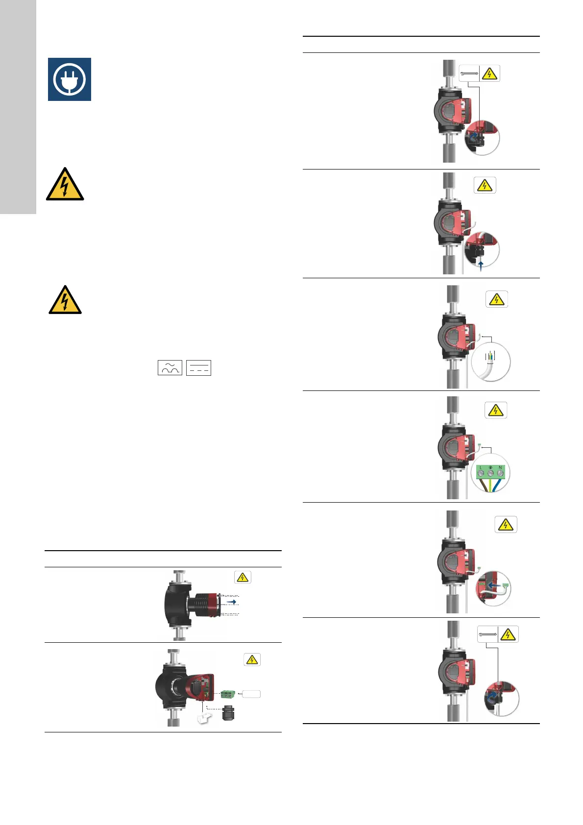
Step Action Illustration
1
Remove the front
cover from the
control box.
Do not remove the
screws from the
cover.
TM05 5530 3016
2
Locate the power
supply plug and
cable gland in the
small cardboard
box supplied with
the pump.
TM05 5531 3016
3
Connect the cable
gland to the
control box.
TM05 5532 3016
4
Pull the power
supply cable
through the cable
gland.
TM05 5533 3016
5
Strip the cable
conductors as
illustrated.
TM05 5534 3016
6
Connect the cable
conductors to the
power supply plug.
TM05 5535 3016
7
Insert the power
supply plug into
the male plug in
the control box.
TM05 5536 3016
8
Tighten the cable
gland.
Refit the front
cover.
TM05 5537 3016
Step Action Illustration
7 mm
20 mm
7 mm
25 mm
Min. Ø 7 mm
Max. Ø 14 mm

 Loading...