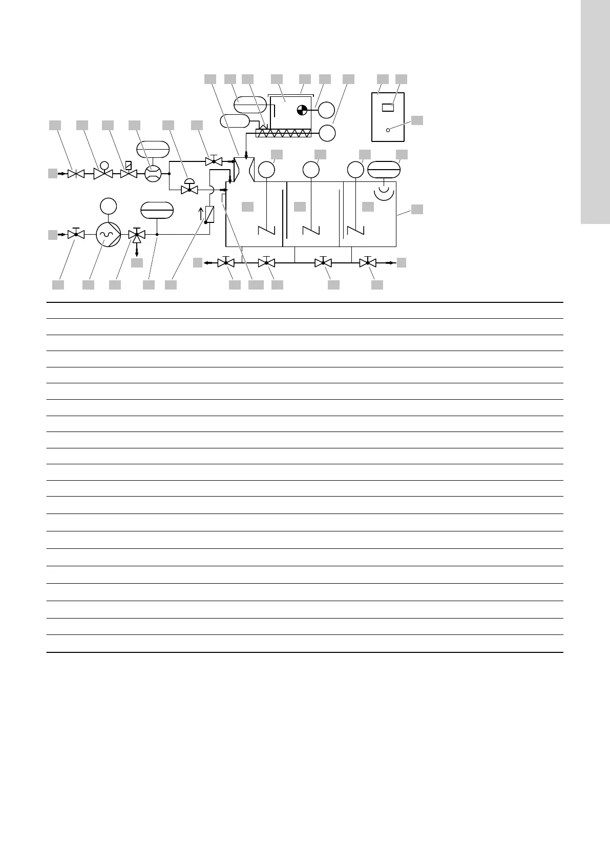
4.4 Piping and Instrumentation Diagram (PID)
FT
PI
LIT
FS
LS
EB
M
M
M
M
M M
F
A
A1
F1 E1
G
E
E2 E3 E4F2 F3 F5 D11F4
F6
A2 A3 A4 A5 A6
D1 B1B2 B5B3 B6 C1
D2 D3 D4 D5
C2
C3
D6
D7 D8 D9
B4
TM071317
Pos. Description Pos. Description
A Water inlet D5 Ultrasonic level sensor
A1 Shut-off valve D6 Three-chamber tank
A2 Pressure reducing valve D7 Mixing chamber
A3 Solenoid valve D8 Maturing chamber
A4 Flow sensor D9 Storage chamber
A5 Regulation valve D11 Overflow outlet
A6 Regulation valve for jet mixer E Withdrawal connection
B1 Heated dosing pipe E1 Ball valve
B2 Dry-material level sensor E2 Ball valve
B3 Cover E3 Ball valve
B4 Dry-material feeder with storage hopper E4 Ball valve
B5 Vibrator F
Liquid-concentrate inlet
*
B6 Gear motor of dry-material dosing screw F1
Ball valve
*
C1 Control cabinet F2
Liquid-concentrate pump
*
C2 Touch screen F3
3-way ball valve
*
C3 Main switch F4
Liquid-concentrate flow sensor
*
D1 Dissolving hopper with jet mixer F5
Non-return valve
*
D2 Stirrer 1 (mixing chamber) F6
Liquid-concentrate calibration outlet
*
D3 Stirrer 2 (maturing chamber) G Drain connection
D4
Stirrer 3 (storage chamber)
*
* Optional component
11
English (GB)