English (GB)
22
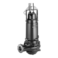
Fig. 14 SE pump, bottom view
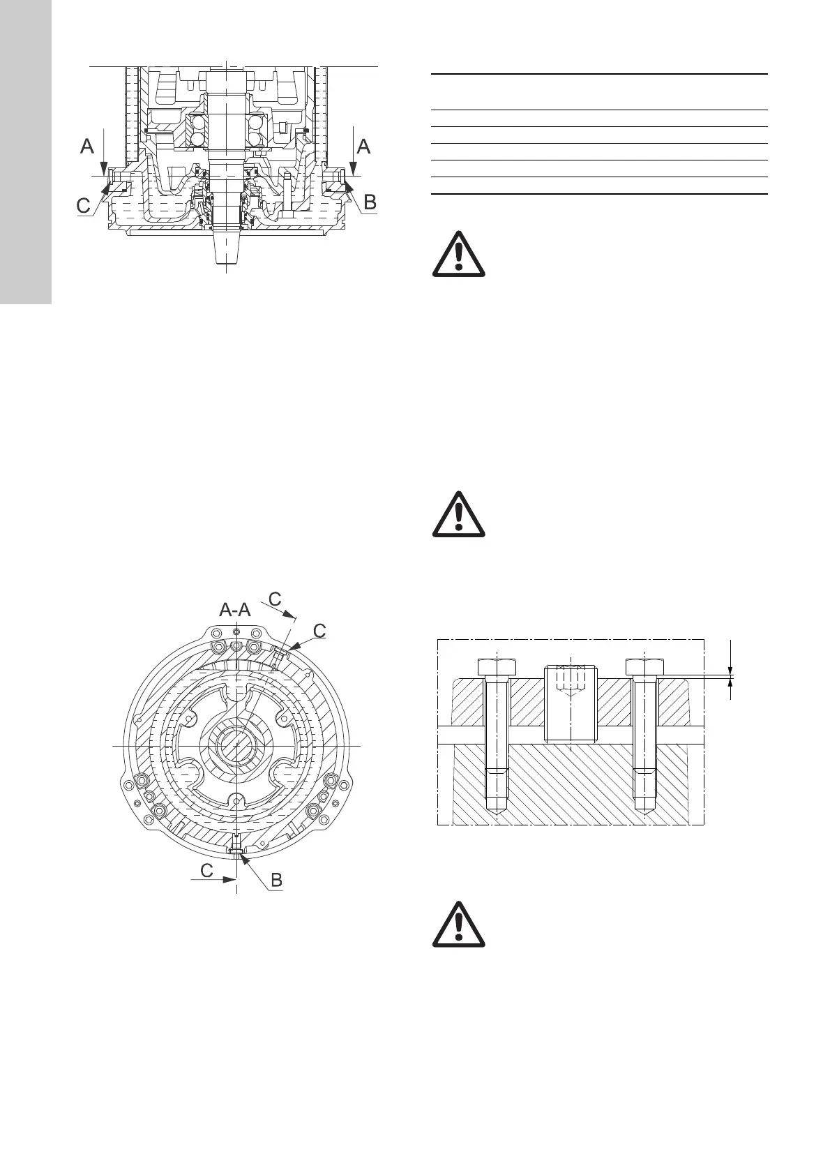
Draining motor liquid, horizontal and vertical installation:
Place a container under the pump to collect all the drained-off
motor liquid; then place the pump in a horizontal position.
Remove screw B, fig. 15, which is facing downwards. Allow all
motor liquid to drain from the housing into the container. Replace
the O-ring with a new ring, insert screw B and tighten securely.
Filling motor liquid, vertical installation:
While the pump is standing vertically, fill the shaft seal housing
with motor liquid through hole A until the motor liquid reaches the
level indicated on fig. 13. Replace the O-rings with new rings,
insert the screws and tighten securely.
Filling motor liquid, horizontal installation:
Place the pump horizontally with plug B mounted and facing
downwards. Fill the shaft seal housing with motor liquid through
hole C until the motor liquid reaches the level indicated on fig. 15.
Replace the O-ring with a new ring, insert screw C and tighten
securely.
Fig. 15 SE pump, sectional horizontal view
10.2 Inspection and adjustment of impeller clearance
Impeller clearance table
The impeller clearance of installation types S and C can be
inspected directly through the pump inlet.
See section 10.2.1 Installation types S and C.
Installation types D and H can be inspected and adjusted with the
pump installed on the base stand and connected to the pipework.
Inspect and adjust the impeller clearance as described in section
10.2.2 Installation types D and H.
10.2.1 Installation types S and C
1. Loosen the set screws by two full turns each.
2. Close the impeller clearance by lightly tightening the fastening
screws diagonally until the impeller touches the pump
housing.
3. Loosen the fastening screws to make the correct gap under
the heads of the fastening screws, see fig. 16, and use the
measure stated in the impeller clearance table above.
4. Tighten the set screws tightly.
5. Tighten the fastening screws diagonally.
Fig. 16 Impeller clearance adjustment, types S and C
TM05 2775 0512
Pressure range
Impeller clearance X
[mm]
E = Extra low pressure 0.9 ± 0.1
L = Low pressure 0.9 ± 0.1
M = Medium pressure 0.6 ± 0.1
H = High pressure 0.6 ± 0.1
S = Super high pressure 0.5 ± 0.1
Warning
Before inspection, make sure that the motor is
switched off and that the mains switch is locked
in position 0.
Warning
Do not use too much force when tightening the
fastening screws as this may damage the bear-
ings. The movement is usual 1 to 3 mm.
TM05 1916 3911
Warning
Do not use too much force when tightening the
fastening screws as this may damage the bear-
ings.
X mm
Set screw
Fastening screw
Fastening screw
 Loading...