English (GB)
15
7. Installation
The extra nameplate label supplied with the pump should be fixed
at the installation site.
All safety regulations must be observed at the installation site, for
instance the use of blowers for fresh-air supply to the tank.
Prior to installation, check the motor liquid level in the shaft seal
housing. See section 10.1 Checking and changing the motor
liquid.
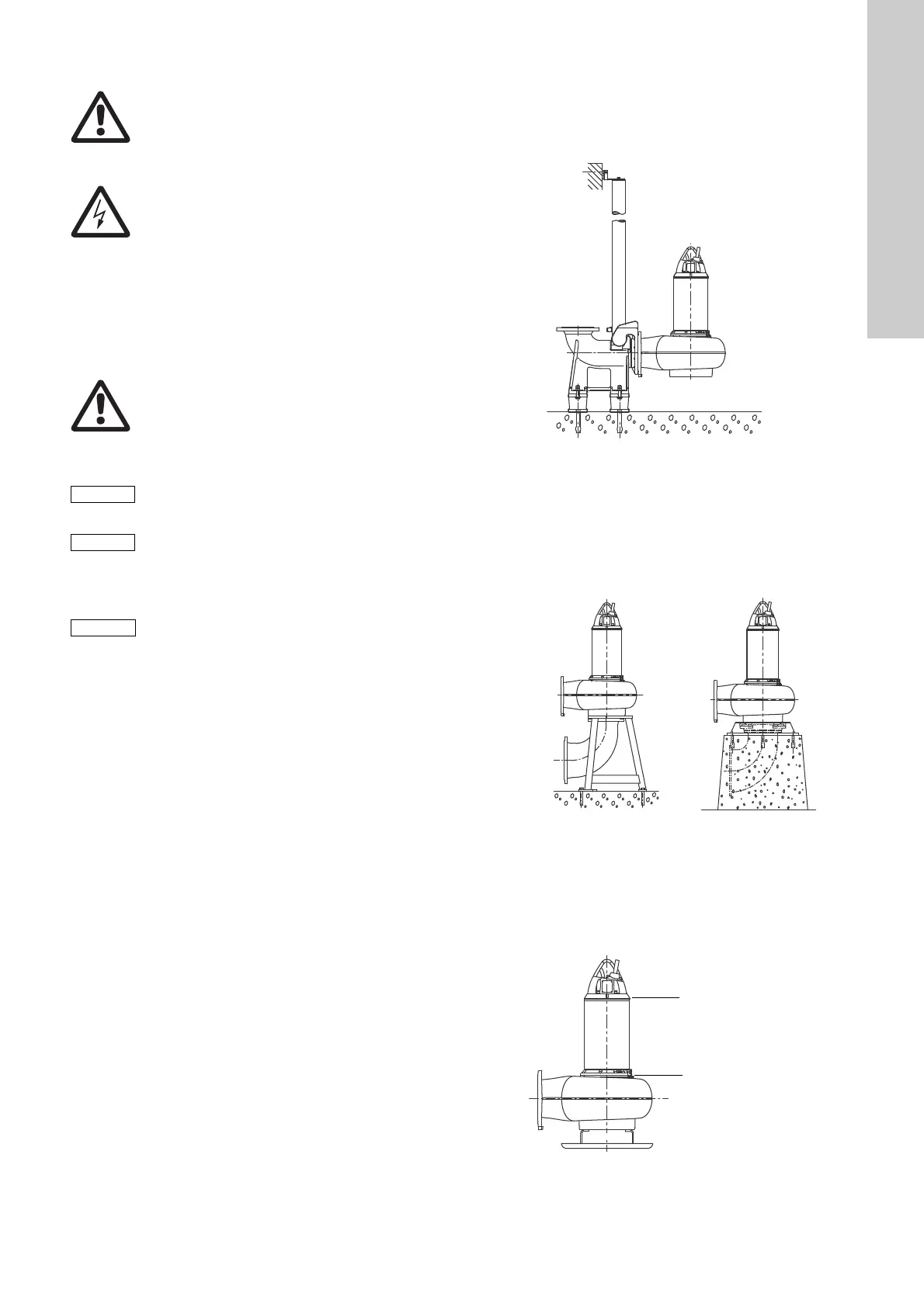
7.1 Installation types
SE/SL pumps, 9-30 kW, are designed for these installation types:
• permanent, vertical, submerged installation in a tank, types S
and C, on auto coupling
• permanent, vertical, dry installation in a pump room, type D,
on base stand or base plate
• temporary, vertical, submerged installation in a tank, types S
and C, on base plate
• permanent, horizontal, dry installation in a pump room, type H.
Figures 5 to 8 show the installation types.
Permanent, vertical installation in a tank
The pump can easily be pulled out of and lowered into the tank
via the guide rails. The liquid level can be set lower for installation
type C than for type S. See fig. 1 and fig. 5.
Fig. 5 Submerged installation on auto coupling
Permanent, vertical installation in a pump room
The pump is fastened to the suction and discharge pipes by
means of flange connections. Pumps with DN 250 or DN 300
flanges must be installed on a concrete foundation (see fig. 6
below to the right).
Fig. 6 Dry, vertical installation on base stand (left) and base
plate on two concrete pedestals (right)
Temporary, vertical installation in a tank
The liquid level can be set lower for type C than for type S.
See fig. 1.
Fig. 7 Submerged, temporary installation
Warning
During installation, always support the pump by
means of lifting chains or place it in horizontal
position to secure stability.
Warning
Before beginning the installation, switch off the
power supply and lock the mains switch in
position 0.
Any external voltage connected to the pump must
be switched off before working on the pump.
Warning
Do not put your hands or any tool into the pump
suction or discharge port after the pump has
been connected to the power supply, unless the
pump has been switched off by removing the
fuses or switching off the mains switch. Make
sure that the power supply cannot be accidentally
switched on.
Avoid pipe tension at flanges and bolts.
The free end of the cable must not be submerged
as water may penetrate through the cable into the
motor.
Make sure that the pipework is installed without
the use of undue force. No loads from the
pipework weight must be carried by the pump.
We recommend the use of loose flanges to ease
the installation and to avoid pipe tension at
flanges and bolts.
Installation types S and C on auto coupling
TM05 2535 0212
Installation type D
TM05 2536 0212 / TM05 2537 0212
Installation types S and C, temporary
TM05 2538 0212
Liquid level for
installation type C
Liquid level for
installation type S
 Loading...