2. SmartFlo Quick guide, SP version
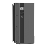
1. Remove the terminal cover.
TM039004
Access to signal terminals
2. Set DIP switch A54 to position "I".
TM039104
Setting contact A54 to current signal "I"
3. Connect the power supply.
TM055867
SmartFlo wiring diagram
Terminal Function
91 (L1)
Single-phase supply
92 (L2)
95/99 (PE) Ground connection
4. Connect the motor.
PUMP
MOTOR
(U)
(V)
(W)
(PE)
96
98
97
99
Yellow
Red
Black
Motor leads
TM081107
Motor connection wiring diagram
5. Plug the terminal strip.
TM039025
Signal terminals
6. Open up the jaw of the terminal by pressing a screwdriver into
the center.
TM081104
Opening up the jaw of the terminal
7. Connect the transducer.
Transducer
Brown (+24 V)
Black (signal)
12
54
TM081106
Pressure transducer wiring diagram
8. Ground the transducer cable as shown below.
TM056003
Grounding the transducer cable
5
English (US)