4. Preliminary configuration
This configuration must be completed before startup.
WARNING
Electric shock
Death or serious personal injury
‐ Touching the electrical parts may be fatal, even after SmartFlo has been switched off. Before starting any work on SmartFlo, the
main supply and other input voltages must be switched off for at least 7 minutes.
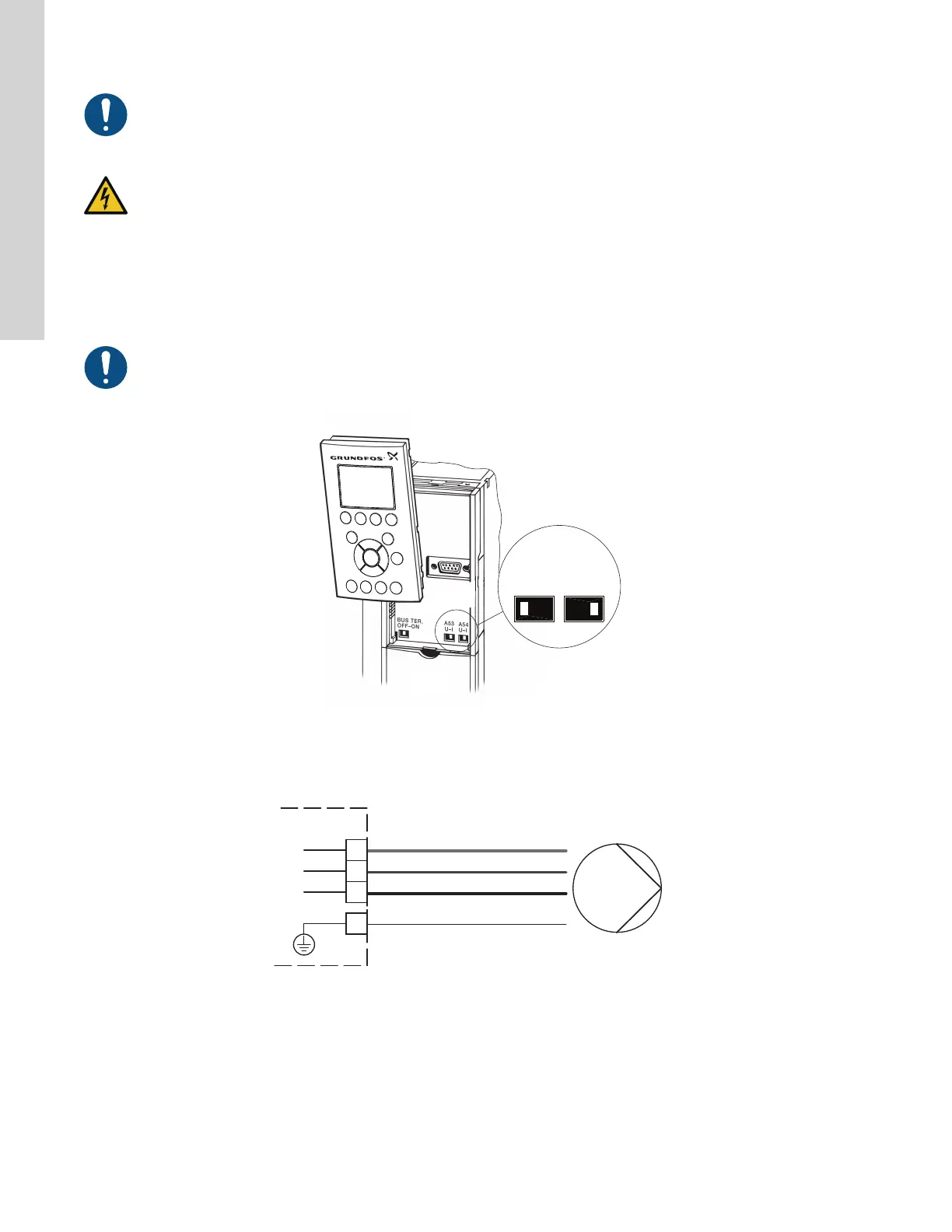
4.1 Setting the analog input, terminal 54
Contact A54 is positioned behind the Local Control Panel (keypad) and used for setting the signal type for the analog input (terminal 54). The
factory setting of the input is voltage signal "U".
If a 0/4-20 mA sensor is connected to terminal 54, the input must be set to current signal "I".
Switch off the power supply before setting contact A54.
TM039104
Setting contact A54 to current signal "I"
4.2 SP motor connection
PUMP
MOTOR
(U)
(V)
(W)
(PE)
96
98
97
99
Yellow
Red
Black
Motor leads
TM081107
Motor connection wiring diagram
8
English (US)