MCD 46 Allgemeiner Teil / General Section
GRUNDIG Service 1 - 3
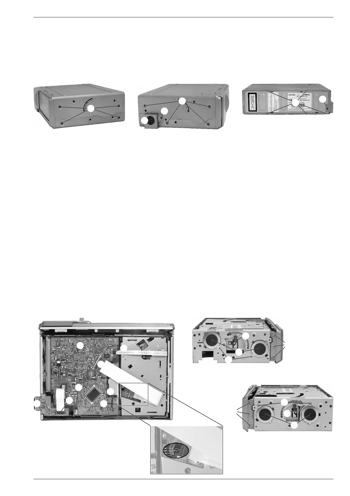
Ausbauhinweise
1. Öffnen des Gehäuses
- 8 Schrauben A (Fig. 1 und 2) herausschrauben.
- 5 Rastnasen B (Fig. 3) ausrasten und Boden und Deckel abneh-
men.
- 2 Schrauben C (Fig. 2 und 3) herausschrauben und die
Abdeckung D der Anschlussplatte abnehmen.
Disassembly Instructions
1. Opening the cabinet
- Undo 8 screws A (Fig. 1 and 2).
- Undo 5 catches B (Fig. 3) and take off bottom and cover.
- Undo 2 screws C (Fig. 2 and 3) and take off the cover D of the
connection board.
A
A
B
C
C
2. Frontblende abnehmen
- Gehäuse öffnen (Pkt. 1).
- 6 Schrauben E (Fig. 5 und 6) herausschrauben und Frontblende
abnehmen.
3. Chassis ausbauen
- Frontblende abnehmen (Pkt. 2).
- Flexprintstecker F (Fig. 4) öffnen.
- 2 Federn G aushängen (Fig. 5 und 6).
- 4 Schrauben H (Fig. 5 und 6) herausschrauben und die 4 Däm-
pfer I (Fig. 5 und 6) abnehmen.
- Chassis herausnehmen.
4. Anschlussplatte ausbauen
- Gehäuse öffnen (Pkt. 1).
- Flexprintstecker F (Fig. 4) öffnen.
- 2 Schrauben J (Fig. 4) herausschrauben und Anschlussplatte
abnehmen.
5. Hauptplatte ausbauen (Fig. 4)
- Gehäuse öffnen (Pkt. 1).
- Schutzlötstelle der Pick-Up-Einheit (Fig. 7) zulöten.
- Flexprintstecker F, K und L öffnen.
- Motoranschlusskabel M ablöten.
- 2 Schränklaschen N aufbiegen.
- 2 Schrauben O herausschrauben und Leiterplatte herausnehmen.
Fig. 1 Fig. 2 Fig. 3
D
F
G
H
I
I
H
G
J
Fig. 4
Fig. 5
Fig. 6
M
K
L
N
E
E
O
O
Fig. 7
2. Removing the front panel
- Open the cabinet (para 1).
- Undo 6 screws E (Fig. 5 and 6) and take off the front panel.
3. Removing the chassis
- Remove the front panel (para 2).
- Open flexprint connector F (Fig. 4).
- Unhinge 2 springs G (Fig. 5 and 6).
- Undo 4 screws H (Fig. 5 and 6) and remove the 4 dampers I (Fig.
5 and 6).
- Take out the chassis.
4. Removing the connection board
- Open the cabinet (para 1).
- Open flexprint connector F (Fig. 4).
- Undo 2 screws J (Fig. 4) and take out the connection board.
5. Removing the main board (Fig. 4)
- Open the cabinet (para 1).
- Close the protective solder joint of the pick up unit (Fig. 7).
- Open flexprint connectors F, K and L.
- Unsolder motor connections M.
- Open the 2 holders N.
- Undo 2 screws O and take out the board.