Allgemeiner Teil / General Section MCD 46
1 - 4 GRUNDIG Service
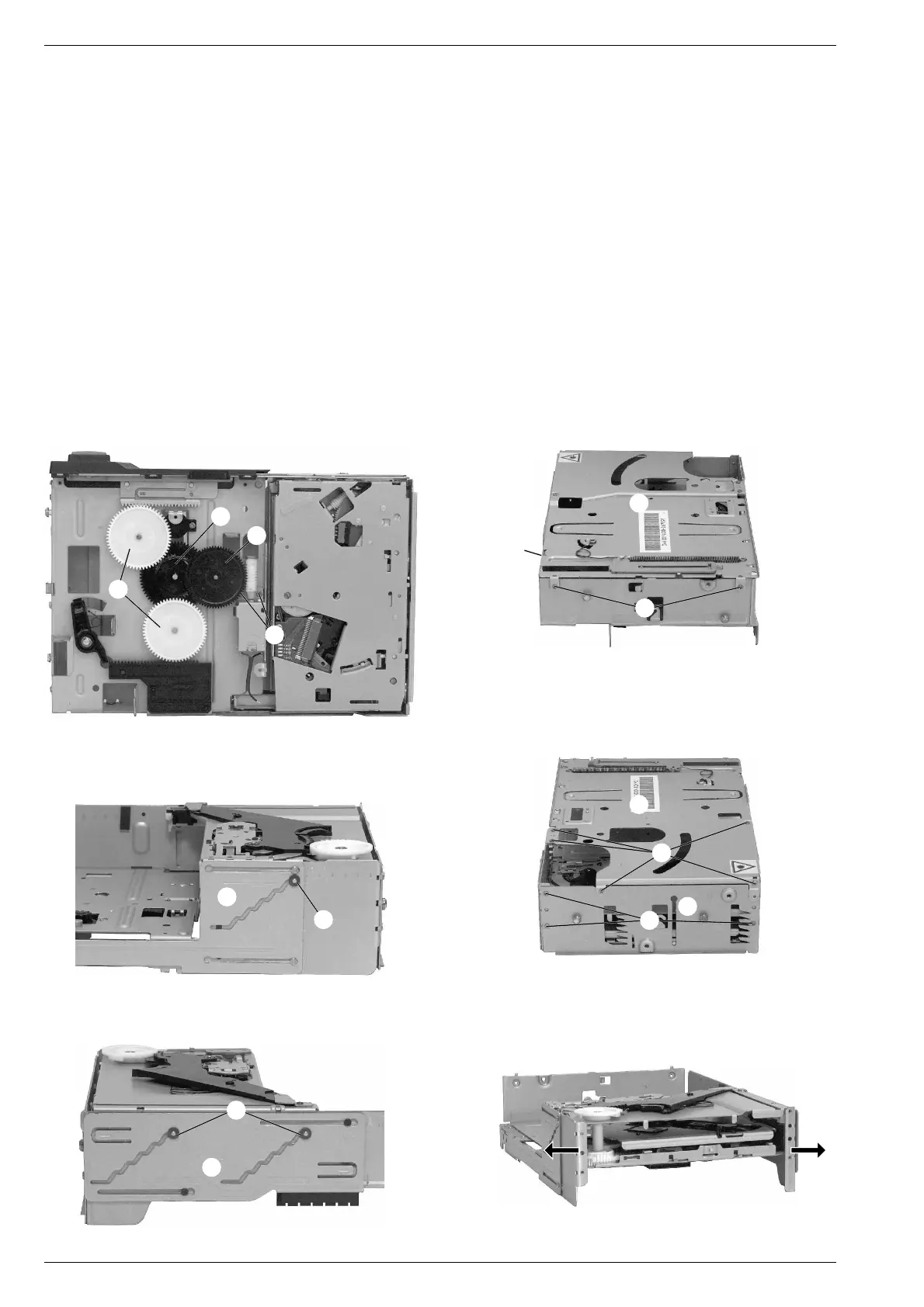
6. Loading-Antrieb zerlegen (Fig. 8)
- Chassis ausbauen (Pkt. 3).
- Hauptplatte ausbauen (Pkt. 5).
- Die Zahnräder P, Q und R können mit einem Schraubendreher
herausgehebelt werden.
- Zum Ausbau des Motors Zahnrad R ausbauen und die 2 Schrau-
ben S herausschrauben.
- Achtung: Wurde wenigstens eines der beiden Zahnräder P aus-
gebaut, beim Zusammenbau darauf achten, dass die 2 Schieber T
(Fig. 10) und U (Fig. 12) in der gleichen Position stehen.
7. Loading-Einheit ausbauen
- Chassis ausbauen (Pkt. 3).
- Hauptplatte ausbauen (Pkt. 5).
- Loading-Einheit in die oberste Position bringen (vgl. Fig. 10 und 12).
- 8 Schrauben V (Fig. 9 und 11) herausschrauben und Oberteil W
abnehmen.
- 3 Schrauben X (Fig. 11) herausschrauben und Seitenteil Y
abnehmen.
- 3 Sicherungsscheiben Z (Fig. 10 und 12) abziehen.
- Die Loading-Einheit kann jetzt durch leichtes Auseinanderbiegen
der Seitenteile herausgnommen werden (Fig. 13).
P
Q
R
S
Fig. 8
Fig. 9
Fig. 11
Fig. 10
Fig. 12
Fig. 13
W
V
V
X
Y
Z
Z
W
V
T
U
6. Disassembling the loading drive (Fig. 8)
- Remove the chassis (para 3).
- Remove the main board (para 5).
- The gear wheels P, Q and R can be pushed out with a screw-
driver.
- Remove gear wheel R and undo the 2 screws S to remove the
motor.
- Attention: If at least one of the gear wheels P had been removed,
take care that both slides T (Fig. 10) and U (Fig. 12) are in the
same position when reassembling.
7. Remove the loading unit
- Remove the chassis (para 3).
- Remove the main board (para 5).
- Move the loading unit to the topmost position (see Fig. 10 and 12).
- Undo 8 screws V (Fig. 9 and 11) and remove the upper part W.
- Undo 3 screws X (Fig. 11) and remove the side part Y.
- Pull off the 3 retainer washers Z (Fig. 10 and 12).
- By bending the side parts slightly apart the loading unit can now
been taken out (Fig. 13).