Allgemeiner Teil / General Section MCD 46
1 - 6 GRUNDIG Service
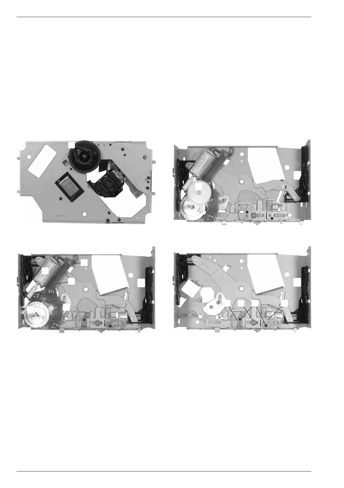
Fig. 21
Fig. 22 Fig. 23
10. Drehteller-Motor M (Fig. 19) ausbauen
- Pick-Up-Einheit ausbauen (Pkt. 9).
- 2 Schrauben N (Fig. 20) herausschrauben und Motor M (Fig. 19)
mit Drehteller herausnehmen.
11. Loading-Antrieb zerlegen
- Laufwerk ausbauen (Pkt. 8).
- Zahnrad O (Fig. 21) mit einem Schraubendreher heraushebeln.
- Zahnrad P herausnehmen (Fig. 22). Achtung: Beim Wiederein-
setzen auf die 2 Schalter Q achten!
- Leiterplatte an Punkt R ausrasten und herausnehmen (Fig. 22).
- 2 Schrauben S (Fig. 22) herausschrauben und Motor T heraus-
nehmen.
- Die 2 Schrauben U herausschrauben und die 2 Federn V und W
abnehmen (Fig. 23).
- Sicherungsscheibe X (Fig. 23) abnehmen.
- Die Einzelteile der Mechanik können jetzt herausgenommen wer-
den.
O
T
R
S
P
Q
V U WX
Fig. 20
N
10. Removing the turn table motor M (Fig. 19)
- Remove the pick up unit (para 9).
- Undo 2 screws N (Fig. 20) and take out motor M (Fig. 19) with the
turn table.
11. Disassembling the loading drive
- Remove the drive unit (para 8).
- Push out gear wheel O (Fig. 21) with a screw driver.
- Take out gear wheel P (Fig. 22). Attention: When reasembling
take care of the 2 switches Q!
- Unhinge the PCB at point R and take it out (Fig. 22).
- Undo 2 screws S (Fig. 22) and remove motor T.
- Undo 2 screws U and remove the 2 springs V and W (Fig. 23).
- Take out retaining ring X (Fig. 23).
- The separate parts of the mechanism can now been taken out.