EasyManuals Logo

GW Instek GDS-3152 User Manual

GW Instek GDS-3152
209 pages
To Next Page IconTo Next Page
To Previous Page IconTo Previous Page
Page #117 background imageLoading...
Page #117 background image
CONFIGURATION
117
Vertical View (Channel)
This section describes how to set the vertical scale, position, and
coupling mode.
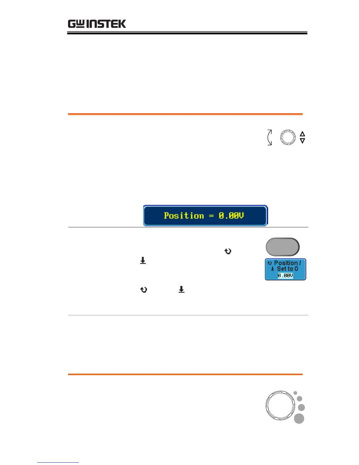
Move Waveform Position Vertically
Panel Operation
1. To move the waveform up or
down, turn the vertical position
knob for each channel.
POSITION
Down
Up
2. As the waveform moves, the vertical position of
the cursor appears at the bottom half of the
display.
View or Reset
Vertical Position
1. Press a channel key. The vertical
position is shown in the Position /
Set to 0 soft key.
2. To change the position, press
Position / Set to 0 to reset the
vertical position or turn the vertical
position knob to the desired level.
CH1
Run/Stop Mode
The waveform can be moved vertically in both
Run and Stop mode.
Select Vertical Scale
Panel Operation
To change the vertical scale, turn the
VOLTS/DIV knob; left (down) or
right (up).
VOLTS/DIV

Table of Contents

Questions and Answers:

Question and Answer IconNeed help?

Do you have a question about the GW Instek GDS-3152 and is the answer not in the manual?

GW Instek GDS-3152 Specifications

General IconGeneral
Bandwidth150 MHz
Sample Rate1 GSa/s
Channels2
Memory Depth10 Mpts
Record Length10 Mpts
Vertical Resolution8 bit
InterfaceUSB, LAN
Time Base Range5 ns/div to 50 s/div
Power Supply100-240 VAC, 50/60 Hz
Display TypeTFT LCD
Waveform Update Rate50, 000 wfm/s
Input Impedance1 MΩ
Trigger TypesEdge, Pulse, Video
Display Resolution800 x 480 pixels
Max Input Voltage±400 V (DC + AC peak)

Related product manuals