EasyManuals Logo

GW Instek GDS-3152 User Manual

GW Instek GDS-3152
209 pages
To Next Page IconTo Next Page
To Previous Page IconTo Previous Page
Page #57 background imageLoading...
Page #57 background image
MEASUREMENT
57
Basic Measurement
This section describes the basic operations required in capturing
and viewing the input signal. For more detailed operations, see the
following chapters.
Cursor Measurement → from page 76
Configuration → from page 87
Before operating the oscilloscope, please see the Getting Started
chapter, page 10.
Channel Activation
Activate Channel
To activate an input channel,
press a channel key.
When activated, the channel
key will light up. The
corresponding channel menu
will also appear.
CH1 CH1
à
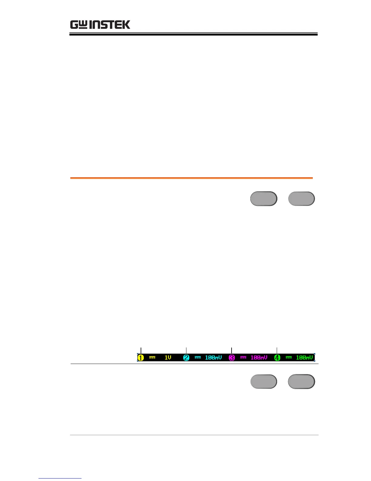
Each channel is associated with the color shown
beside the VOLTS/DIV dial: CH1: yellow, CH2:
blue, CH3: pink and CH4: green.
When a channel is activated, it is shown above the
bottom menu system.
CH1 CH3CH2 CH4
De-activate
Channel
To de-activate a channel, press
the corresponding channel key
again. If the channel menu is
not open, press the channel key
twice (the first press shows the
Channel menu).
CH1 CH1
à

Table of Contents

Questions and Answers:

Question and Answer IconNeed help?

Do you have a question about the GW Instek GDS-3152 and is the answer not in the manual?

GW Instek GDS-3152 Specifications

General IconGeneral
Bandwidth150 MHz
Sample Rate1 GSa/s
Channels2
Memory Depth10 Mpts
Record Length10 Mpts
Vertical Resolution8 bit
InterfaceUSB, LAN
Time Base Range5 ns/div to 50 s/div
Power Supply100-240 VAC, 50/60 Hz
Display TypeTFT LCD
Waveform Update Rate50, 000 wfm/s
Input Impedance1 MΩ
Trigger TypesEdge, Pulse, Video
Display Resolution800 x 480 pixels
Max Input Voltage±400 V (DC + AC peak)

Related product manuals