GDS-800 Series Digital Storage Oscilloscope Operation Manual
26
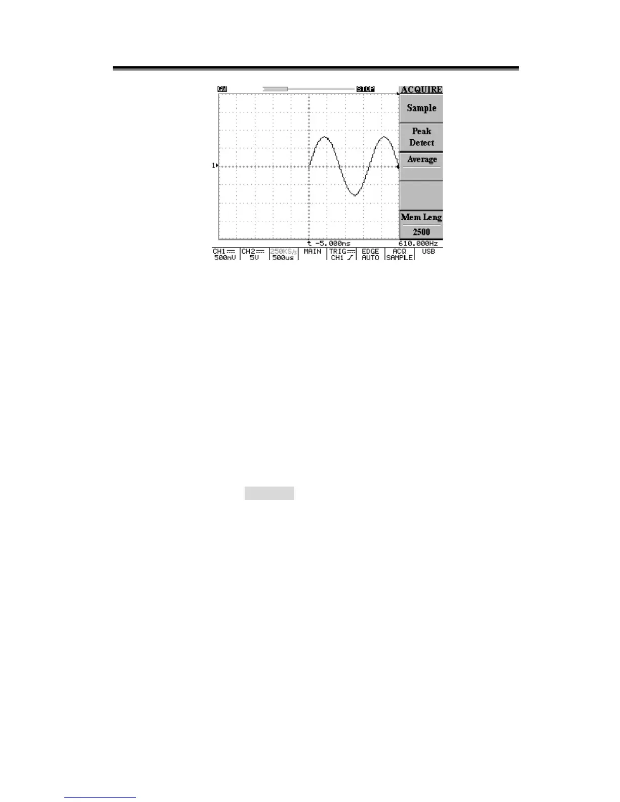
Figure 5-10: Decreasing “delay trigger indicator” shifts the waveform to the right
The sum of left-most “delay trigger indicator” and right-most “delay trigger indicator”
is equal to 10ms (5ms+5ms). Therefore, the above formula is approved.
The maximum “exploring” factor for this oscilloscope is 7 faster “time/div” setting on
the sample rate of original acquired waveform. In the meantime, the “exploring”
factor is only based on the 500 points of memory length.
Users should check the sample rate in advance, and examine Table 5-2 (the row of
memory length=500) to find out the interrelated timebase afterward. After the
interrelated timebase is confirmed, just count 7 faster “time/div” setting from Table
5-2. The maximum “exploring” factor is appeared. In an easy way, users may just
rotate the horizontal’s TIME/DIV knob directly. The oscilloscope will count
automatically.

 Loading...