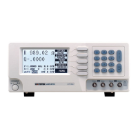
Do you have a question about the GW Instek LCR-800 Series and is the answer not in the manual?
| Brand | GW Instek |
|---|---|
| Model | LCR-800 Series |
| Category | Measuring Instruments |
| Language | English |
Details on safely unpacking the instrument after delivery and checking for transit damage.
Instructions for verifying the correct line voltage and fuse replacement for safe operation.
Specifies the normal ambient temperature range and advises against strong magnetic or electric fields.
Ensures proper ventilation and covers important warnings regarding product usage and radio interference.
Explains the four-wire measurement structure and the use of cable sets and test fixtures.
Procedure for connecting the power cord and activating the instrument using the POWER button.
Details on zeroing open and short circuits to correct test cable/fixture errors for accurate measurements.
Explains how to enter and navigate the LCR meter's menu system for programmable functions.
Explains how to select and display primary and secondary measurement parameters simultaneously.
Defines equivalent circuits and provides suggested test conditions for various components.
Describes the VALUE, DELTA%, and DELTA display modes for measurement results.
Allows entry of a 'Nominal Value' used as a basis for DELTA or DELTA % measurement results.
Details the three measurement speeds (SLOW, MEDIUM, FAST) and their trade-off between accuracy and speed.
Configures various measurement parameters including bias voltage, frequency, test voltage, and more.
Explains the internal (2V) and external (0-30V) bias voltage modes for testing components.
Details how to select test frequencies, available frequencies, and their calculation for LCR meters.
Enables selection of DQ in PPM for improved resolution of Dissipation or Quality factor.
Covers the range of test voltages and the procedure for programming the desired test voltage.
Provides a constant voltage feature with a 25 Ohm source resistance, affecting accuracy.
Allows avoiding range switching when DUT is removed in continuous mode, reducing test time.
Enables averaging of measurements (1-255) to enhance accuracy, increasing measurement time.
Details the functions for saving and recalling current measurement conditions into 100 memory blocks.
Provides accuracy details for R, L, C, D, and Q measurements, including model-specific variations.
Details the available test frequencies and their ranges for different LCR meter models.
Describes the VALUE, DELTA%, and DELTA display modes for measurement results.
Lists the measurement speeds (SLOW, MEDI, FAST) for specific LCR models and their timings.
Explains that L, C, or R equivalent SERIES or PARALLEL circuits can be selected.
Explains the AUTO mode for continuous measurement and MANUAL mode for holding results.
Details the averaging function for measurements (1-255) in AUTO or MANUAL modes.
Specifies the test voltage ranges for different LCR meter models and step increments.
States that the instrument has 100 memory blocks for storing measurement conditions.
Describes the internal 2V and external up to 30VDC bias voltage for capacitors.
Details the LCD monitor specifications: 240x128 dot matrix with adjustable contrast.
Mentions the 3V lithium battery for memory backup and its replacement interval.
Explains the 'OVER-01' message for impedance issues and provides solutions to resolve it.
Provides instructions for cleaning the instrument safely, avoiding harsh chemicals and abrasives.
Details the procedure and cautions for replacing the 3V lithium battery for memory backup.
Outlines the steps to proceed with BIN functions for sorting components using the LCR meter.
Details the various conditions and parameters required for setting up BIN sorting.
Configures the measurement mode (e.g., C/D, C/R, L/Q, R/Q) for component sorting.
Selects the equivalent circuit representation as Series (SER) or Parallel (PAR).
Selects the measurement speed from FAST, SLOW, or MEDIUM.
Configures display output as BIN results, test values (VAL), or no display (OFF).
Allows key-in of the desired testing frequency through the panel keyboard.
Allows key-in of the desired testing voltage through the panel keyboard.
Configures the internal bias (INT) or external bias (EXT) mode.
Selects the measurement range value from 1 to 4.
Enables or disables the Constant Voltage (C.V) feature.
Sets the delay time for measurements in milliseconds (0-99999ms).
Sets the averaging value for measurements.
Defines the steps for setting BIN ranges, including Tot_BIN, C_Nom.Val, Max, Min, and D_Max/D_Min values.
Sets the total number of BINs to be used for sorting, from 1 to 13.
Enters the nominal value for the component being sorted.
Sets the upper limit for the sorting range.
Enters the positive tolerance percentage for the sorting range.
Sets the lower limit for the sorting range.
Enters the negative tolerance percentage for the sorting range.
Sets the maximum value for the secondary parameter in sorting.
Sets the minimum value for the secondary parameter in sorting.
Step-by-step guide to establish an online connection between the LCR meter and PC via RS-232.
Details the pin configurations for the D-SUB 9-pin female connectors for PC and LCR meter.





 Loading...