6
DEUTSCHENGLISH FRANÇAIS ITALIANO ESPAÑOL NEDERLANDS
PORTUGUÊS
SVENSKA
© HAAG‑STREIT AG, 3098 Koeniz, Switzerland ‑ HS‑Doc. No. 1500.7221019.04030 / 2024 – 04
Listed European Authorized
Representative
Medical Device
Rotating knob on camera sym-
bol = 70 % of the light goes to
the camera
Diaphragm selection knob
Slit illumination Background illumination
Strong permanent magnets On (Power)
MET Listed Mark with approval
for USA and Canada
2 Intended purpose / intended use
The Imaging Module 910 was developed exclusively for the Haag-Streit slit lamp BQ
900, which can be used to produce digital photographs and videos (optionally avail-
able in 3D) for documentation of the eye.
3 Introduction
3.1 Description of the device
The system allows for creation of digital images and videos. An optional licence en-
ables processing of digital pictures and videos in 3D (stereo). Without a licence pro-
cessing is in 2D (mono). The divider mirror can be switched off with a switch (rotat-
ing knob) so that 100% of the light reaches the eyepiece. With the release module, it
is possible to release images or videos and to change the camera's exposure time
without letting go of the joystick. The connector box enables viewing a live stream
on a connected monitor without EyeSuite. The position sensor is an optional access-
ory for automatically switching the system on/off depending on the table position.
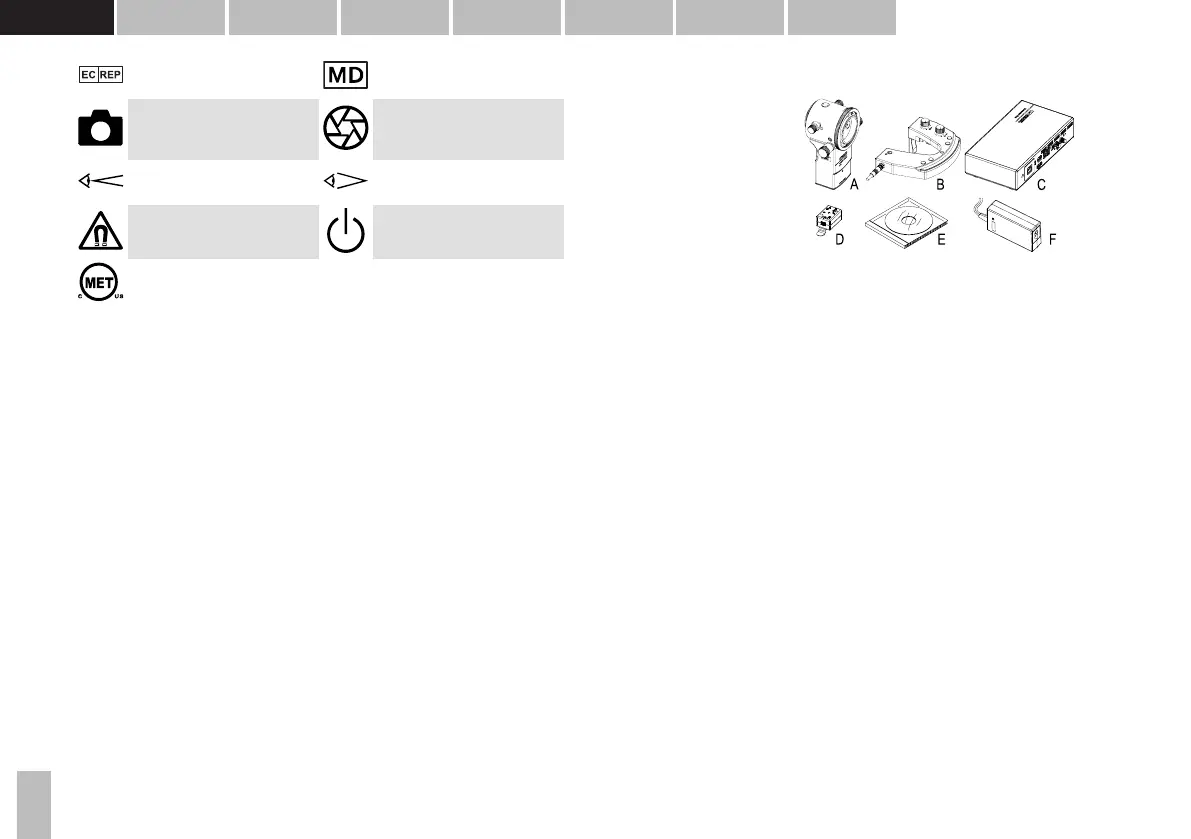
3.2 System components
The Imaging Module 910 is a
system made up of the following
main components:
A. Camera module CM04
B. Release module RM03
C. Connector box CB01
D. Position sensor PoS01
1)
E. EyeSuite software
2)
F. Power supply
1) Optional accessory
2) EyeSuite Imaging extension can be optionally activated for a surcharge
3.3 LED illumination (prerequisite)
1. Lamp cable with special connection plug for LI01 plus / LI02 plus
2. LED illumination head with background illumination (see separate instructions
for use)
3. Fiber optic line for background illumination
4. Headrest (see separate instructions for use)
5. Rail cover
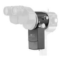
3.4 Camera module CM04
6. Camera module CM04
7. Beam splitter switch (rotating knob)
8. Diaphragm selection (rotating knob)
9. Operational control LED
10. Cable clamp
11. Cable CXP (CM04 to CB01)
3.5 Release module RM03
12. Sticker left/right identification
13. Release module RM03
14. Cable distributor
15. Cable clip