8
DEUTSCHENGLISH FRANÇAIS ITALIANO ESPAÑOL NEDERLANDS
PORTUGUÊS
SVENSKA
© HAAG‑STREIT AG, 3098 Koeniz, Switzerland ‑ HS‑Doc. No. 1500.7221019.04030 / 2024 – 04
4 Device assembly / installation
WARNING!
• Do not modify this device without authorization of the manufacturer.
Installation and repairs may only be performed by trained special-
ists.
• Contact your Haag-Streit representative for installation, repairs and
modification work on the system. The contact details are available at
www.haag-streit.com.
• Only original Haag-Streit spare parts may be used.
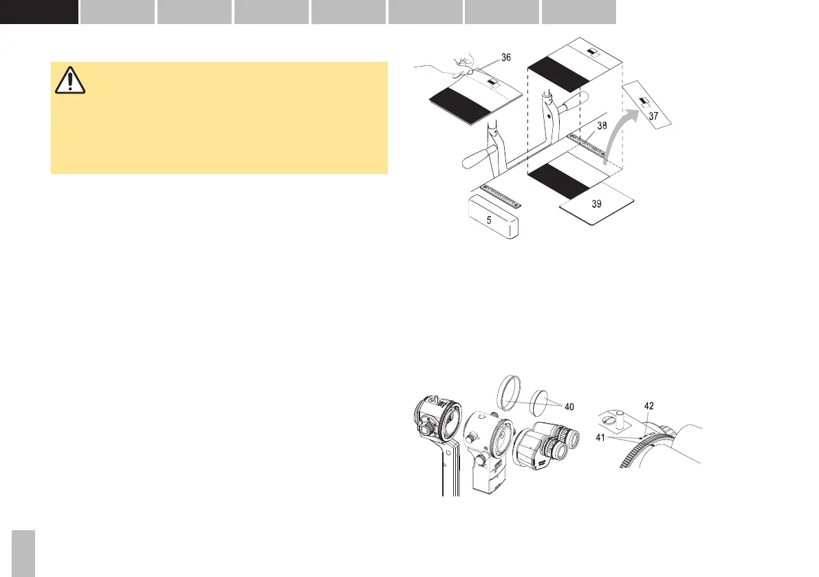
4.1 Placement of adhesive label for the automatic left/right de-
tection
36. Protective film
37. Rest of the sticker
38. Roller rail
39. Gliding plate
• Remove rail cover (5) and place slit lamp aside. Clean surface of table.
• Remove protective film (36) from the back of the adhesive label. Carefully start
at the corner opposite the black surface.
• Position the sticker against the right roller rail (38) and the gliding plate (39).
Press firmly on the white/black surface, press away any air bubbles.
• Carefully tear off the remainder of the adhesive label (37) (the 'positioning tool')
along the perforation.
• Reassemble the slit lamp and rail cover.
4.2 Connecting the CM04 in the beam path
40. Cover caps
41. Marking points
42. Arrow (lock)
• Disassemble the breath shield.
• Remove the black and white cover caps (40).
• Align the marking points (41) on the upper side of the parts to be connected.
• Turn the locking ring in the direction of the arrow shown (42) to tighten.