EasyManua.ls Logo

Hach Lange CL17 User Manual

Hach Lange CL17
60 pages
To Next Page IconTo Next Page
Page #1 background imageLoading...
Page #1 background image
DOC023.52.80034
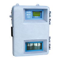
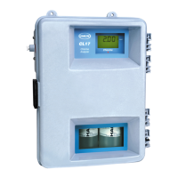
CL17 Chlorine Analyzer
USER MANUAL
02/2014, Edition 9
© Hach Company, 2000, 2001, 2004, 2008, 2009-2011, 2013, 2014. All rights reserved. Printed in the U.S.A./Germany

Table of Contents

Questions and Answers:

Hach Lange CL17 Specifications

General IconGeneral
Measurement PrincipleColorimetric
Resolution0.01 mg/L
Wavelength515 nm
Power Supply100 - 240 VAC, 50/60 Hz
Weight5.5 kg
ParameterChlorine
Detection Limit0.02 mg/L
Reagent TypeDPD
Sample Temperature5 - 40 °C
Operating Temperature5 - 40 °C
Output4-20 mA

Summary

Section 1 Specifications

Electrical Specifications

Covers power requirements, connection methods, installation category, and protection class.

Optical and Performance Specifications

Section 2 General Information

Safety Information Overview

Crucial safety instructions, including hazard definitions and the importance of following manual guidelines.

Precautionary Label Identification

Explains the meaning of various safety labels attached to the instrument and their significance.

Section 3 Installation

Wall Mounting the Instrument

Procedures and considerations for securely mounting the analyzer case onto a wall.

Plumbing Connections Guide

Instructions for making sample inlet and drain connections using appropriate fittings and tubing.

Sample Line and Conditioning

Installing the Sample Line

Guidance on selecting an optimal sampling point and installing the sample line to ensure representative measurements.

Sample Conditioning System

Information on using the sample conditioning kit to filter and prepare samples for analysis.

Electrical Connections and Setup

Electrical Connection Points

Identifies the locations for power, alarm, and network connections on the instrument enclosure.

Power Connection Procedures

Instructions for safely making the main power connections to the analyzer.

Instrument Wiring Guidelines

Details on connecting wires for power, alarms, and recorder outputs, including wire gauge.

Voltage Selection and Alarm/Recorder Connections

Voltage Selection for Operation

How to set the internal switch for 115V or 230V operation and fuse information.

Alarm Relay Connections

Instructions for wiring the two alarm relays to external devices or control systems.

Section 4 System Startup

Reagent Installation and Preparation

Instructions for installing buffer and indicator solutions and preparing the indicator reagent.

Section 5 Operation

Calibration Procedures

Step-by-step guides for calibrating the analyzer using standards or comparison methods.

Section 6 Maintenance

Section 7 Troubleshooting

Troubleshooting Guide by Symptom

A table listing common symptoms, probable causes, and corrective actions for instrument issues.

System Alarm Indicators

Explains system alarm messages, their indications, and the necessary steps for resolution.

Appendix A Network Interface Card

Related product manuals