55
Appendix A Network Interface Card
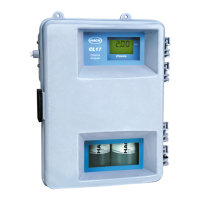
The CL17 analyzer can be purchased with a Network Interface Card. This allows the
analyzer to be attached via the AquaTrend
®
software to one master AquaTrend Interface,
one Serial Input/Output (SIO) Module, one Signal Output Module (SOM) with two relays
and one recorder output, and two MOD I/Os. Remote AquaTrends and Digital Display
Modules are not supported. Refer to the AquaTrend Interface Instruction Manual for
complete details on configuring the Hach network.
1. Route a Hach-approved network cable to the CL17 Analyzer. Route the network
cable through the middle wiring access hole in the CL17 housing. (This hole is also
used for routing Recorder output wiring.) Use appropriate hardware to maintain the
NEMA 4X and IP66 ratings.
2. Strip the ends of the network cable. Strip back the wire insulation ¼ inch as shown in
Figure 24.
3. Insert each bare wire end into the 3-pin connector using the information in Table 12.
Make sure the wire insulation is seated against the connector. Do not leave any bare
wire exposed.
4. Plug the terminated cable into J1 on the Interface Card.
5. Reattach the access panel to the instrument enclosure with the two screws.
6. Reapply power to the CL17 Analyzer.
A.1 Attach the analyzer to the network using an AquaTrend interface
1. Make network connections from the CL17 Analyzer to the AquaTrend Network. It is
recommended to make connections at the junction box. Be certain to connect the
cable shield.
2. From the Master AquaTrend Interface add the CL17 Analyzer to the network:
a. Press the
MENU key and select NETWORK MENU.
b. Select ADD DEVICE. The AquaTrend display will show the instrument name and
version number.
c. When the display prompts
ADD DEVICE, press ENTER. The AquaTrend display will
show
CL17 CONFIGURING DEVICE. PLEASE WAIT.
d. After the sensor is added to the network a message will be displayed with the
name of the sensor. Press
ENTER to accept the displayed sensor name. Press the
MENU key to return to the main menu.
Figure 24 Proper wire preparation
Table 12
Position Signal Wire color
1NET_AWhite
2NET_BGreen
3 GND Shield
 Loading...