23
Installation
3.8.5 Recorder output connections
The recorder output is a 4–20 mA current-source output. Make recorder connections with
twisted-pair shielded wire and connect the shield at the recorder, controlled component
end or at the analyzer end. Do not connect the shield at both ends of the cable.
Make wiring connections at the analyzer end as follows:
1. Make sure no power is supplied to the instrument.
2. Remove the Customer Access Cover (refer to Figure 9 in the manual).
3. Strip the insulation on each wire back ¼-inch. Refer to Figure 14.
Note: Use a twisted-pair, shielded cable. Use of non-shielded cable may result in radio frequency
emission or susceptibility levels higher than allowed.
4. Route the wire through an available strain relief.
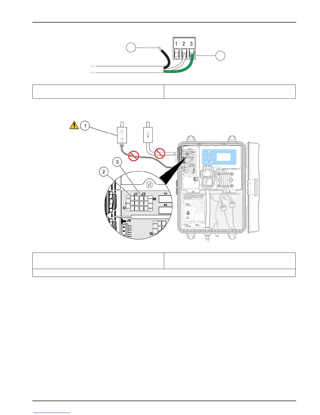
Figure 14 Proper wire preparation and insertion
1 Strip ¼ in. of insulation 2 Seat insulation against connector with no bare wire
exposed.
Figure 15 Alarm connections
1 Current to the relay contacts must be limited to 5 amps.
Note: Make sure no power is supplied to the instrument.
3 J2 alarm connections terminal block: Terminal 1 = COM;
Terminal 2 = NO; Terminal 3 = NC
2 J1 alarm connections terminal block: Terminal 1 = COM; Terminal 2 = NO; Terminal 3 = NC
 Loading...