41
Maintenance
6.2 Unscheduled maintenance
6.2.1 Fuse replacement
The T, 2.5A, 250V fuse used in this instrument is used for both 115V and 230V operation.
DANGER
Electrocution hazard. Remove power from the instrument when removing or
installing a fuse.
DANGER
Fire hazard. For continued protection against fire, replace the fuse only with a fuse
of the same type and rating.
Fuse replacement procedure:
1. Make sure there is no power supplied to the instrument. the instrument power switch
does not remove power from the fuses, Power must be disconnected remotely to
remove power from the fuses.
2. Remove the customer access cover.
3. Locate the fuse holders (near the terminal strip in the customer wiring compartment).
Refer to Figure 13 on page 22.
4. Remove the two fuses (F1 and F2) and replace them with two new fuses with the
same specifications (T, 2.5A, 250V). Refer to Parts and accessories on page 49.
5. Reinstall the customer access cover and resupply power.
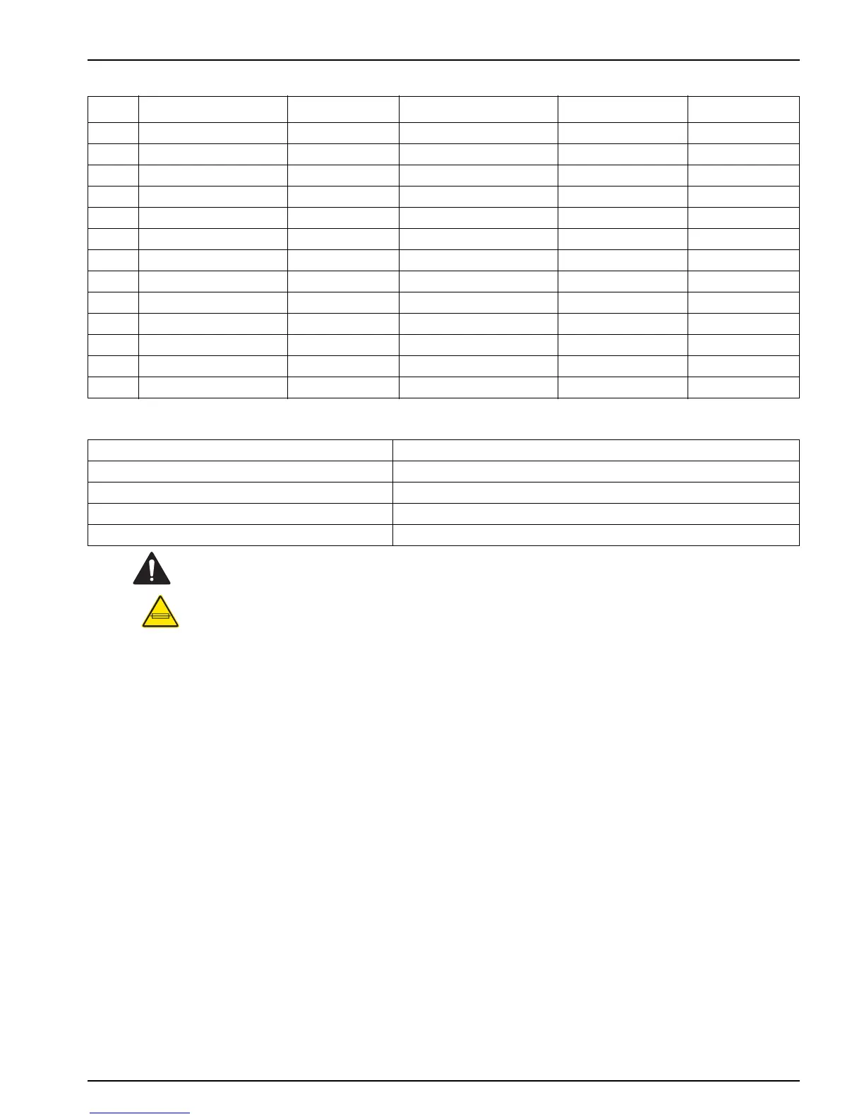
Table 7 Replacement Tubing Lengths for Figure 21
Item Description Length (Qty) From... To... Item Number
11/8"
ID, 1/4" OD 4.5 inches (1) Pump Body Out Colorimeter 43293-00
2 1/32" ID, 3/32" OD 7.0 inches (2) Pump Body Out Y-Fitting 44253-00
3 1/16" ID, 3/32" OD 2.0 inches (4) Pump Body In Pump Body Out 42717-00
4 0.062 ID, 0.125" OD 6.0 inches (2) Reagent Bottle Cap Pump Body In 42076-00
5 0.062" ID, 0.125" OD 6.0 inches (2) Reagent Bottle Cap Reagent Vent Fitting 42076-00
6 1/32" ID, 3/32" OD 7.0 inches (2) Reagent Bottle Bottom Reagent Bottle Cap 45524-00
7 1/8" ID, 1/4" OD 7.0 inches (1) Sample Bypass Tee Pump Body In 43293-00
8 1/8" ID, 1/4" OD 1.5 inches Sample Bypass Tee Sample Inlet Fitting 43293-00
9 1/4" OD x 0.04 W, Black varies (1) Sample Conditioning Out Case Fitting 30616-00
10 1/2"
ID varies (1) Instrument Drain Customer Drain (not supplied)
11 1/32"
ID, 3/32" OD 3 inches Sample Bypass Tee Drain fitting 44253-00
12 1/32" ID, 3/32" OD 1.0 inch (1) Y-Fitting Colorimeter 44253-00
13 0.500” ID, 11/16” OD 12 inches Colorimeter Drain Fitting 54108-00
Table 8 Drain, air purge, sample-in, and enclosure locations
A Air purge, 0.01 CFM at 20 PSIG max, ¼ in. O.D. tube
B Case drain, ½ in. I.D. tube
C Sample drain, ½ in. I.D. tube
D Sample in, 5 PSIG max, ¼ in. O.D. tube
EEnclosure
 Loading...