22
Installation
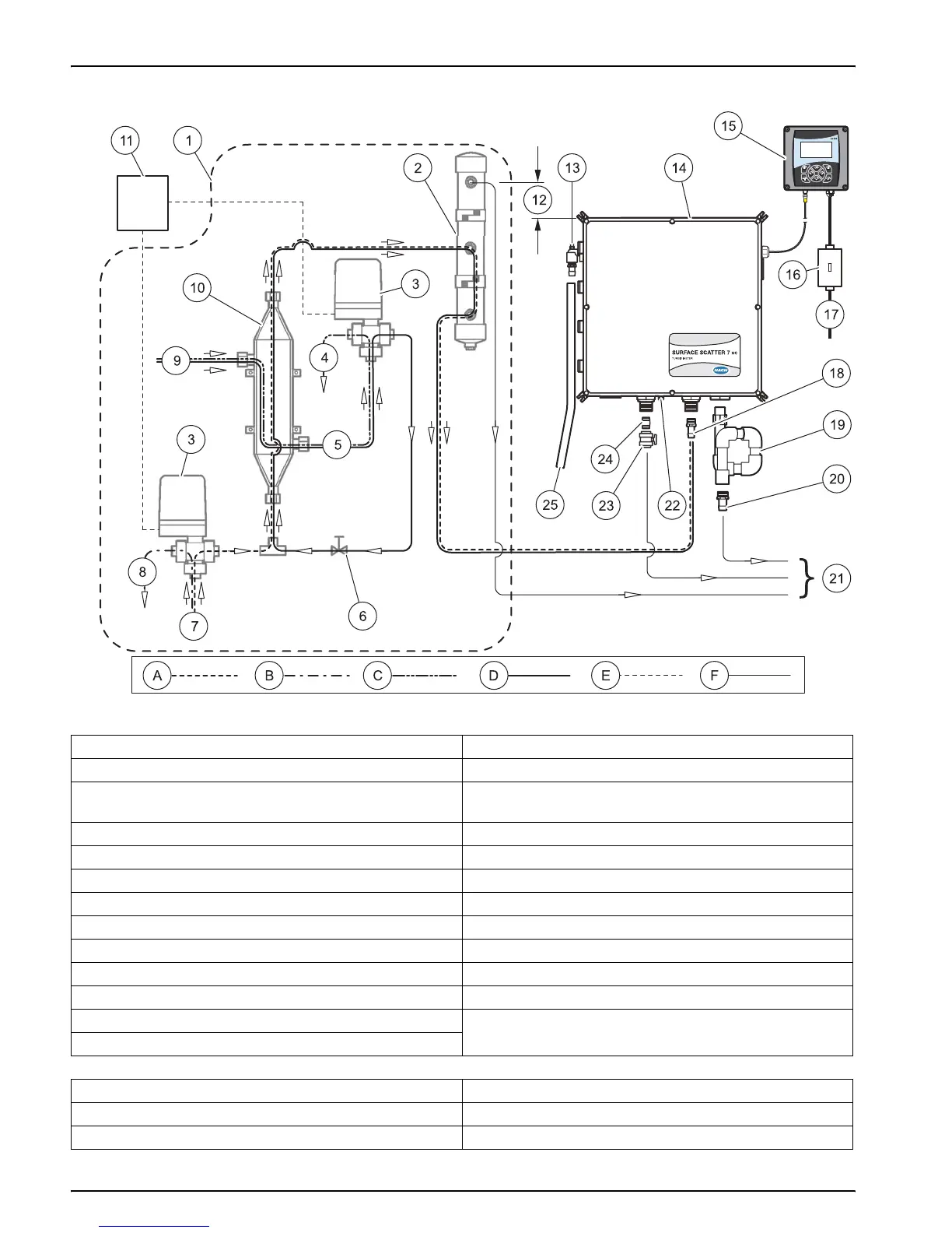
Figure 12 SS7 sc-HST plumbing diagram
1 Optional items 14 Sample unit
2 Bubble trap 15 sc100
3 3-way ball valve (Auto Flush Kit) 16 Customer supplied power on/off switch box (NEMA 4X)
required for agency compliance
4 Cooling water to drain 17 Power in for sc controller platform
5 Cooling water out 18 ¾-in. NPT adapter (supplied)
6 Flow control valve 19 Drain Trap (Customer-supplied)
7 Sample in 20 1-in. NPT adapter (supplied)
8 Sample bypass during flush cycle 21 To drain
9 Cooling water in 22 ¼-in. air purge fitting (50 SCFH instrument air max)
10 Heat exchanger 23 Ball valve (supplied)
11 Electrical box connection 24 ¾-in. NPT nipple (supplied)
12 127 mm (5 in.) minimum 25 Customer supplied hose to drain
13 Customer supplied air for flow multiplier
A Sample during normal operation D Cooling water during auto flush
B Sample bypass during auto flush E Electrical
C Cooling water in normal operation F Drain