23
Installation
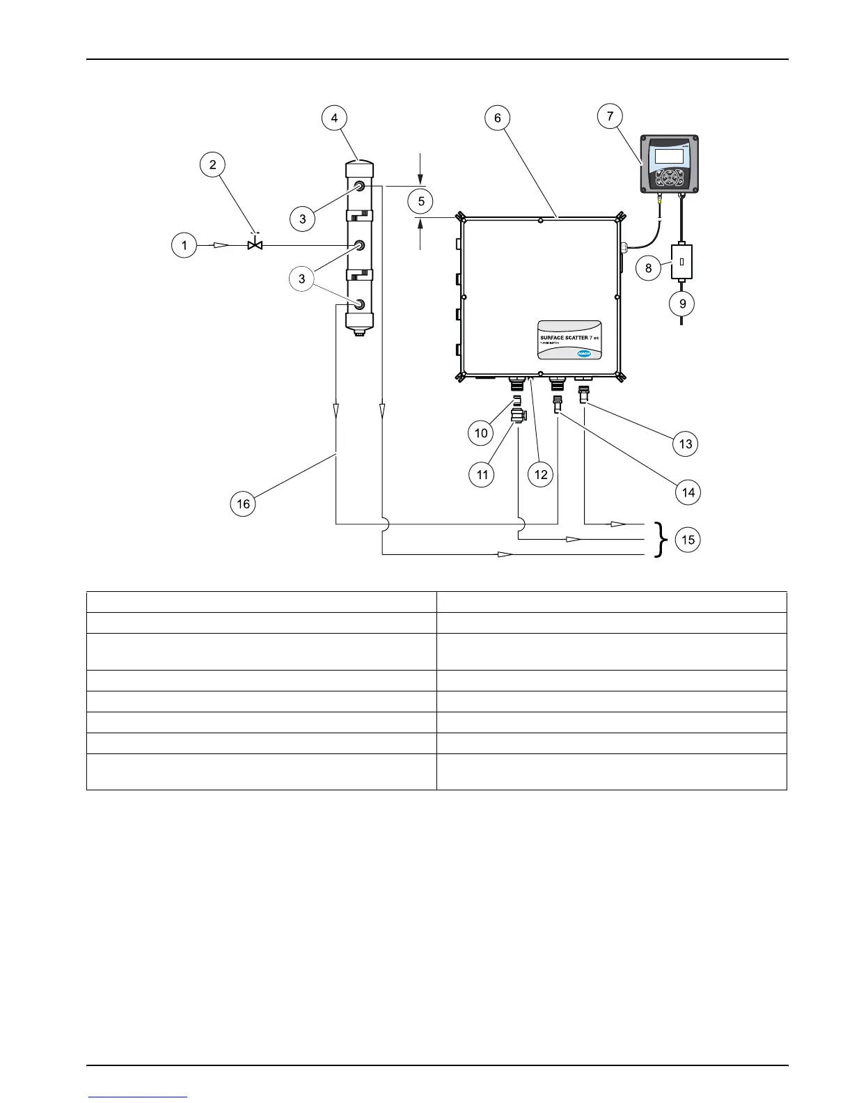
Figure 13 SS7 sc plumbing diagram
1 Sample in 9 Power in for the sc controller platform
2 Flow control valve (recommended) 10 ¾-in. NPT nipple (supplied)
3 ¾-in.NPT x ¾-in. ID Hose Adapter
(supplied with bubble trap)
11 Ball valve (supplied)
4 Bubble trap (optional) 12 ¼-in. air purge fitting (50 SCFH instrument air max)
5 127 mm (5 in.) minimum 13 1-in. NPT nipple (supplied)
6 Sample unit 14 ¾-in. NPT nipple (supplied)
7 sc100 (shown; SS7 sc is also compatible with sc1000) 15 To drain
8 Customer supplied power on/off switch box (NEMA 4X)
required for agency compliance
16 ¾-in. ID hose (customer supplied)