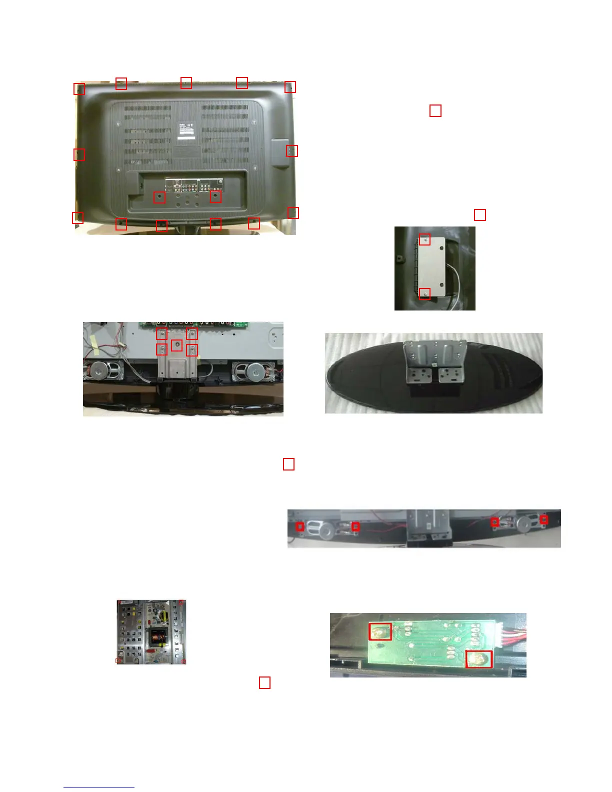
6. DISASSEMBLY INSTRUCTIONS
1. Remove the back cover
A. Remove the fifteen screws indicated in
the figure by the
B. Once the back cover has been
detached you will have to disconnect
the side A/V Board by either
disconnecting connector CNC2 on the
mainboard or detaching the side A/V
board from the back cover by removing
the 2 screws indicated by
2. Remove the Pedestal
A. Lay the unit down on its face
B. Remove the five screw indicated by the from the pedestal to
detach it.
3. Remove the speakers
Each speaker is attached by 4 screws
4. Remove the Power Supply P.C.B. 5. Remove the Remote Receiver P.C.B.
Remove the 4 screws indicated by the
P.C.B. is located at the bottom center of
the front cabinet.
Remove the 2 screws
 Loading...