39
Table 8-4 IEC Recommended Separation of RF Communication Equipment
Recommended separation distances between portable and mobile RF communications equipment and the HALYARD* Pain Management System
The HALYARD* Pain Management System is intended for use in an electromagnetic environment in which radiated RF disturbances are controlled. The customer or the
user of the HALYARD* Pain Management System can help prevent electromagnetic interference by maintaining a minimum distance between portable and mobile
RF communications equipment (transmitters) and the HALYARD* Pain Management System as recommended below, according to the maximum output power of the
communications equipment.
Rated maximum output power of
transmitter
W
Separation distance according to frequency of transmitter
m
150 kHz to 80 MHz
d = [1.17] √P
80 MHz to 800 MHz
d = [1.17] √P
800 MHz to 2.5 GHz
d = [2.33] √P
0.01 0.12 0.12 0.23
0.1 0.37 0.37 0.74
1 1.17 1.17 2.33
10 3.69 3.69 7.38
100 11.7 11.7 23.3
For transmitters rated at a maximum output power not listed above, the recommended separation distance d in meters (m) can be determined using the equation applicable
to the frequency of the transmitter, where P is the maximum output power rating of the transmitter in watts (W) according to the transmitter manufacturer.
NOTE 1: At 80 MHz and 800 MHz, the separation distance for the higher frequency range applies.
NOTE 2: These guidelines may not apply in all situations. Electromagnetic propagation is aected by absorption and reection from structures, objects and people.
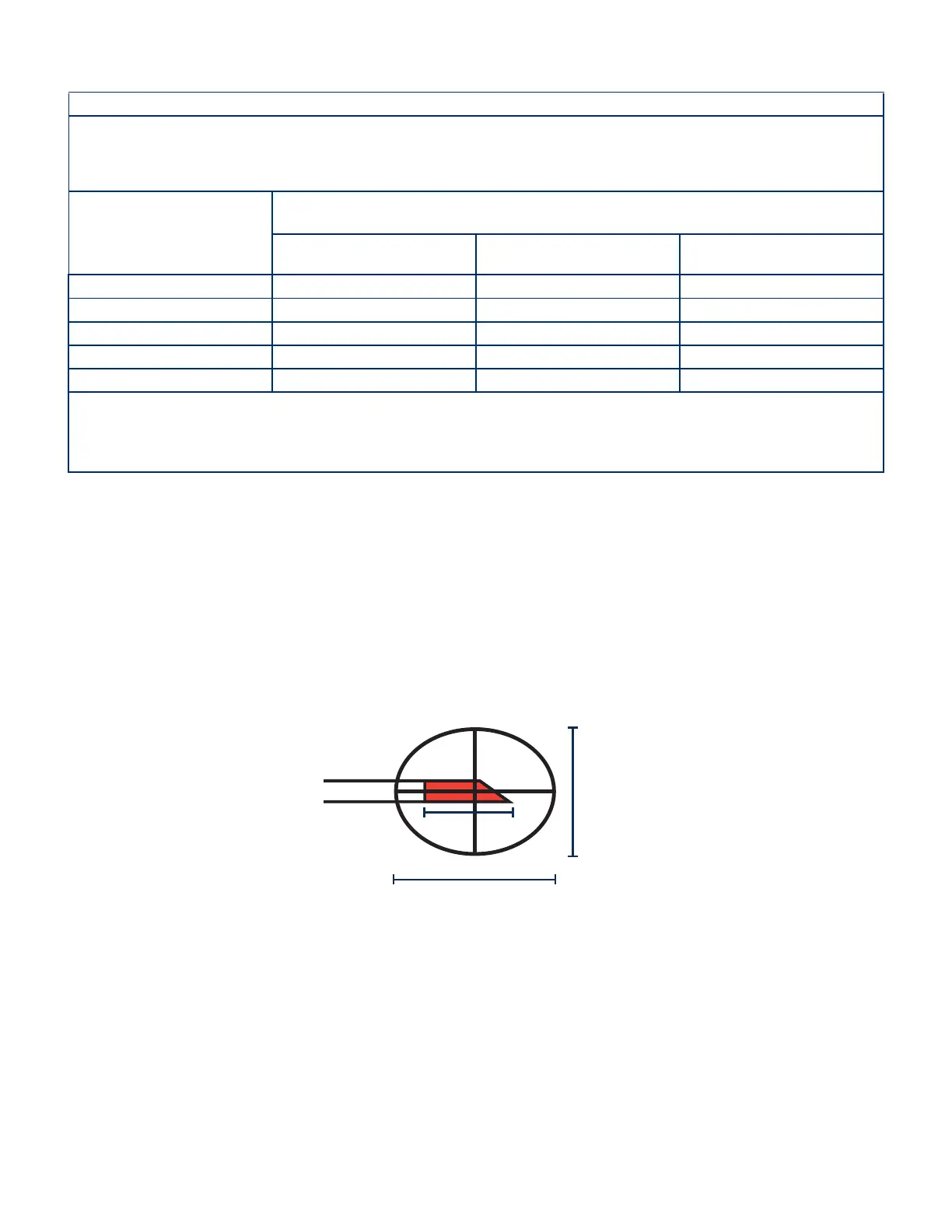
9 Standard RF Lesion Size
Lesion size and shape is determined by numerous factors including:
• cannula active tip length
• cannula active tip diameter
• impedance of tissue
• current intensity
• length of time that energy is applied
One published approximation method for lesion size and shape describes a lesion as a prolate spheroid in shape with the major axis = 2 x length of the active tip and the minor
axis = 2/3 the major axis.
1
This approximation is valid for active tip lengths of up to 5 mm.
Eg: based on Active tip = 5 mm (0.197”)
Major axis = 10mm (0.394”)
Minor axis = 6.7mm (0.263”)
For active tip lengths in excess of 5 mm, the active tip diameter will primarily dictate the minor axis dimension of the lesion. The maximum minor axis dimension will not
typically exceed 8 mm for 18 to 22 gauge cannulae.
Note: In Multi-RF Auto Temp mode, maintain a minimum distance of 10 mm between probe tips and ensure that the probe tips do not touch. So long as this distance is maintained, all
lesions formed will be non-contiguous.
1
ORGAN, L.W.: Electrophysiologic Principles of Radiofrequency Lesion Making. Appl. Neurophys. 39:69-76
Minor Axis = (2/3)M
Major Axis (M) = 2L
L
Avanos Exhibit 2069 Page 39
Medtronic, Inc. v. Avanos Medical Sales, LLC
Case IPR2020-0089