22
!
!
Bandsaw
N2-38 / N3800 / N4400
6.4 Electrical connection
Note: The machine‘s circuit box may only be opened with the express consent of the FELDER service team. Vio-
lating this stipulation shall render the right to make claims under the warranty null and void.
Attention! Risk of material damage!
Before hooking up the machine to the power supply, compare the specifications on the data plate with those of
the electrical network. Only hook up the machine if the two sets of data correspond to each other.
Warning! Danger! Electric current!
All electrical repairs must be carried out by a qualified electrician.
Attention! Personal injury and damage to property!
For protection against electric shock, the machine must be protected by the operator with a protective device
(residual current circuit breaker and/or overcurrent protection device).
The dimensioning of the current value for the overcurrent protection device and residual current circuit breaker
can (e.g.) be taken from the circuit diagram.
The switch-off times according to EN 60204-1 must be observed.
Checking the loop impedance and the suitability of the overcurrent protective device must take place at the
location where the machine is to be commissioned!
Electrical connection requirements
• The machine must be earthed with electrical conductors.
• The voltage fluctuations in the mains supply may not
exceed ±10 %.
• The switch cabinet must be fitted with a circuit breaker (DIN
VDE 0641).
Number of terminals: 3 (three phase current motors)
• The unit must only be used in TN-Systems (neutral
connected to earth)! (only 3x400V)
• Safeguarding/Power supply cord:
see “Technical data”
• The power supply cable must be protected against damage
(e.g. armoured conduit).
• The power supply cable must be laid in such a way so it
does not overbend or chafe and there is no risk of tripping
over it.
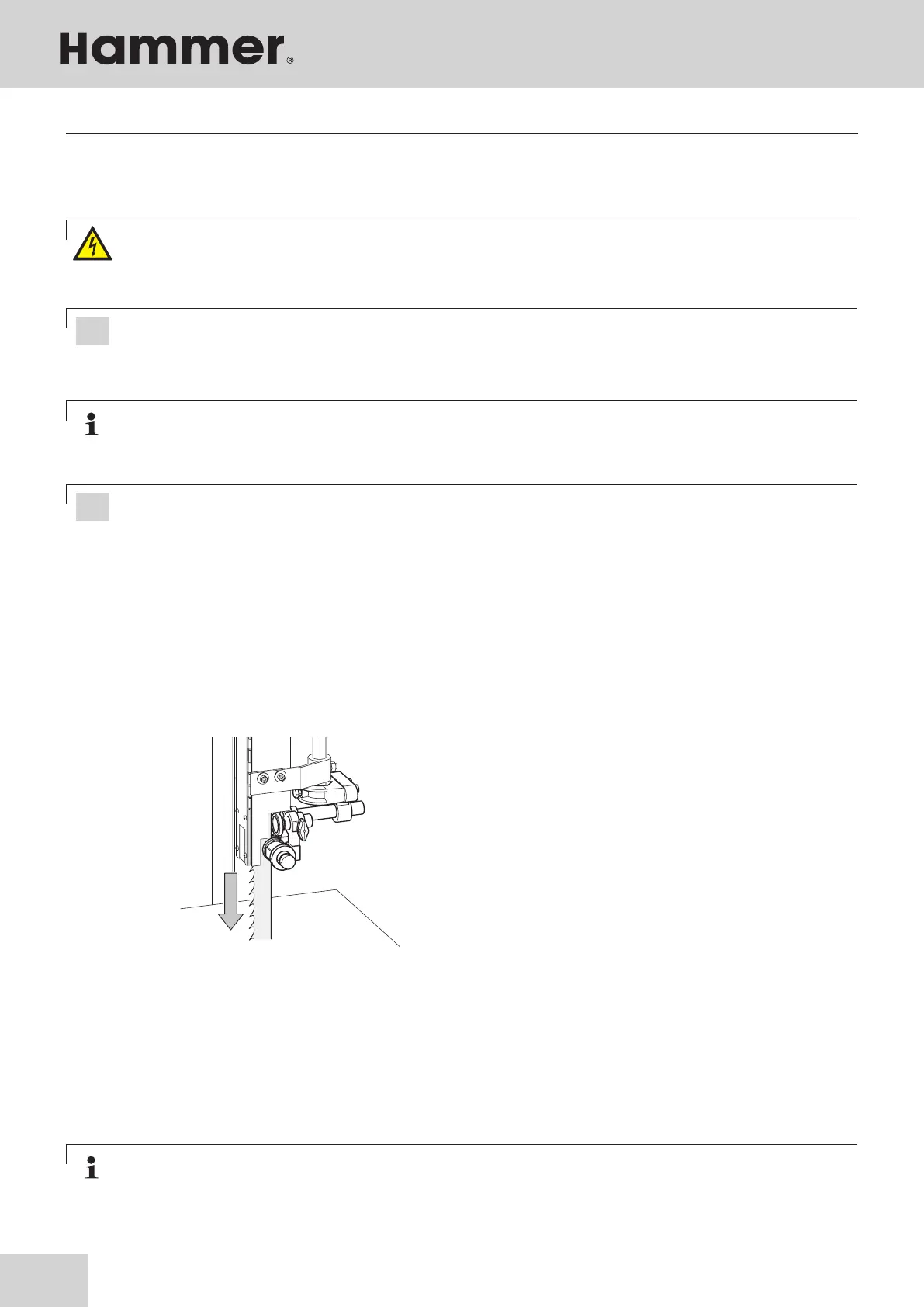
Fig. 1-12: Direction of the Motor rotatation
1. Connect the plug to the power supply.
2. Switch on and let the machine run briefly.
3. While the motor is running, check its direction of
rotation.
4. Should a change in the direction of rotation be nec-
essary, switch the two phases on the power cable.
Note: The machine‘s power cable is delivered with an open cable end, i.e. without a plug.
The operator is responsible for fitting the machine‘s power cable with a suitable plug in accordance with any
country’s specific regulations.
The electrical outlet must have the appropriate socket (for a three-phase alternating current motor, CEE).
Setup and installation