Do you have a question about the Hamtronix ELEKTRA 2500 and is the answer not in the manual?
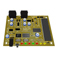
Details the pin assignments and color coding for various connectors. Includes CN1, CN2, and CN3.
Specifies signals, colors, and descriptions for the Repeater (RPT) connector.
Details signals, colors, and descriptions for the Auxiliary (AUX) connector.
Lists signals and descriptions for the Remote connector, including logic outputs.
Guides initial power-up and connection checks for the controller, including squelch adjustment.
Explains the function of various trimpots for adjusting audio input and output levels.
Provides steps to adjust audio levels for optimal retransmission fidelity.
Describes the status indication of the LEDs on the controller board.
Details the timed fan control feature and its activation criteria.
Explains how to connect and interface the controller with virtual assistants like Google Home.
Explains the role of pre-emphasis and de-emphasis circuits in FM audio transmission.
Provides guidance on achieving optimal audio quality for retransmission.
Details how to obtain necessary audio signals from various transceivers.
Explains how to select the de-emphasis setting on the controller.
Defines the format and structure for entering DTMF commands to control the repeater.
Master switch to enable or disable the repeater transmitter.
Sets the duration the transmitter remains active after a signal drops.
Determines the delay before a courtesy tone sounds after signal drop.
Sets the length of the courtesy tone.
Selects the frequency for the courtesy tone.
Chooses the type of courtesy tone, including single, multi-tone, and special tones.
Determines how often the courtesy tone automatically changes.
Sets the type of confirmation sound for valid commands.
Defines the action taken when the time-out limit is exceeded.
Allows testing of IDs and checking controller version and serial number.
Enables or disables CTCSS requirement for repeater operation.
Enables or disables CTCSS requirement for auxiliary port operation.
Sets the frequency for the built-in PL/CTCSS decoder.
Determines the interval for transmitting voice or CW IDs.
Chooses which type of ID (CW, voice message, smart voice) will be transmitted.
Sets the frequency for the CW ID tone.
Determines the transmission speed for CW IDs.
Allows programming of the CW ID message content.
Guides on recording voice messages for ID purposes.
Configures the alarm input for violation detection, triggering a siren sound.
Sets up the monitor input for AC voltage or logic state monitoring.
Enables or disables the repeater port, affecting signal acceptance.
Configures the link port for different operational modes like auxiliary, control, or cross-repeater.
Enables a test mode for the transmitter, allowing carrier or tone transmission.
Enables simplex repeater mode for recording and playback of signals.
Sets the maximum allowed duration for each transmission.
Configures general purpose remote outputs, including enable and pulse modes.
Allows or denies DTMF command acceptance via the repeater port.
Mutes repeater audio upon DTMF tone reception to prevent command repetition.
Allows changing the default 4-digit password for security.
Restarts the microcontroller with user programmed values, similar to power up.
Restarts the microcontroller and all functions to factory default values.
Security measure to prevent accidental erasure of voice messages.
Defines the action assigned to the multi-function button S1.
Sets the duration for recorded voice messages.
Determines priority for voice IDs when the repeater is busy.
Enables Super User mode, bypassing password requirements.
Allows custom creation of courtesy tones by setting frequency, duration, and interval.
Details three methods for performing a full reset to restore default settings.
| Brand | Hamtronix |
|---|---|
| Model | ELEKTRA 2500 |
| Category | Controller |
| Language | English |