Technical Manual VERSION 2.0 -10-18-2018
10
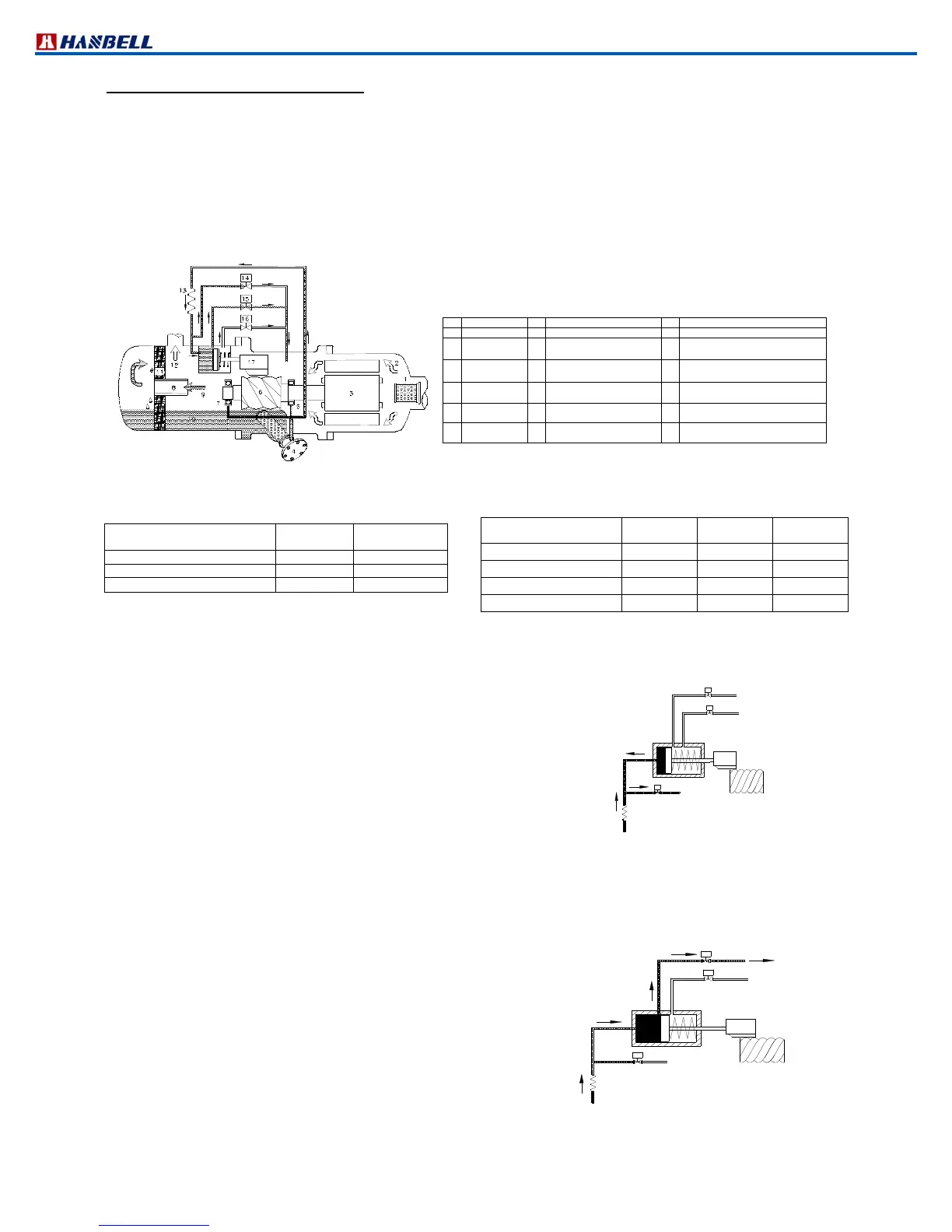
2.7 3 or 4step capacity control system
There are two (For RC2100, RC2140, RC2180) or three (for the rest 23 models) solenoid valves installed on the
compressor that control the compressor capacity from minimum capacity (please refer to chapter 2.2 for different
minimum capacity of each model) to full load (100%). There are two / three normally closed (NC) solenoid valves used
to control the various required capacity. For the compressor with 3step / 4step capacity control system, it is usual to
use the sequence of min.%66%100% / min.%50%75%100% to load the capacity of compressor and to use the
sequence of 100%66%min.%/100%75%50%min% to unload the capacity. If min% capacity is kept for a long time,
the problem of oil return, motor cooling, high discharge temperature need to be solved by adding accessories such as
oil level switch for monitoring the oil level, liquid injection devices for cooling motor coil and reducing discharge
temperature.(Figure 8). Min% is recommended for start and stop only, not for longtermed operation.
Figure 8 4step capacity control
Note: For 3step or 4step capacity control system, Hanbell equips normallyclosed (NC) solenoid valves as standard
accessory. If normallyopened (NO) solenoid valves are preferred instead, please specify it to Hanbell when placing
order.
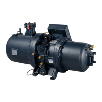
a. min% capacity
When starting the compressor, SV25%/33% solenoid valve is
energized and the piston is in min% capacity position, so even the oil
coming from the oil sump is continuously injecting into the cylinder
through the capillary, the highpressured oil in the cylinder bypasses
directly into the suction port, so the piston is kept in its initial position.
※
It is strongly recommended to energize SV25%/33% solenoid valve for 1~3 minutes before starting the compressor
to ensure the slide valve is in min% position.
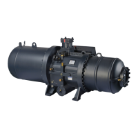
b. 50% capacity (omitted for RC2100, 140,180)
When SV50% solenoid valve is energized by the temperature
controller, the highpressure oil in the oil sump flows into the cylinder
due to the closing of min% valve that pushes the piston moving toward
the position where a hole at exactly 50% position drains the oil back to
the suction side then the piston is held on that position.
No.
Component No.
Component No.
Component
1 Suction filter 7 Discharge bearings 13
Capillary
2
Gas in(low
pressure)
8 Oil separator baffle 14
Solenoid valve (min. %),
SV 25%/33%
3 Motor 9
Gas out(high pressure with
oil)
15
Solenoid valve (50% of full
load),SV50%
4
Oil filter
cartridge
10
Lubricant 16
Solenoid valve (75%/66% of full
load),SV75%/66%
5
Suction
bearings
11
Oil separator demister 17
Slide valve
6 Male rotor 12
Gas out(high pressure without
oil)
*
For RC2100, 140 & 180 the
SV 50%omitted
RC2100,140,180 capacity
control system
SV33%(NC)
SV66%(NC)
100
of full load
not energized
not energized
66% of full load not energized
energized
33%(for start)
energized not energized
RC2200~1530 capacity
control system
SV25%(NC)
SV75%(NC)
SV50%(NC)
100% full load
not energized
not energized
not energized
75% of full load
not energized
energized not energized
50% of full load
not energized
not energized
energized
25%(for start)
Energized not energized
not energized
SV 50% OFF
SV75% OFF
SV25%/33% ON
Figure 9 Min% Capacity
SV75% OFF
SV25%/33% OFF
Figure 10 50% Capacity