Technical Manual VERSION 2.0 -10-18-2018
9
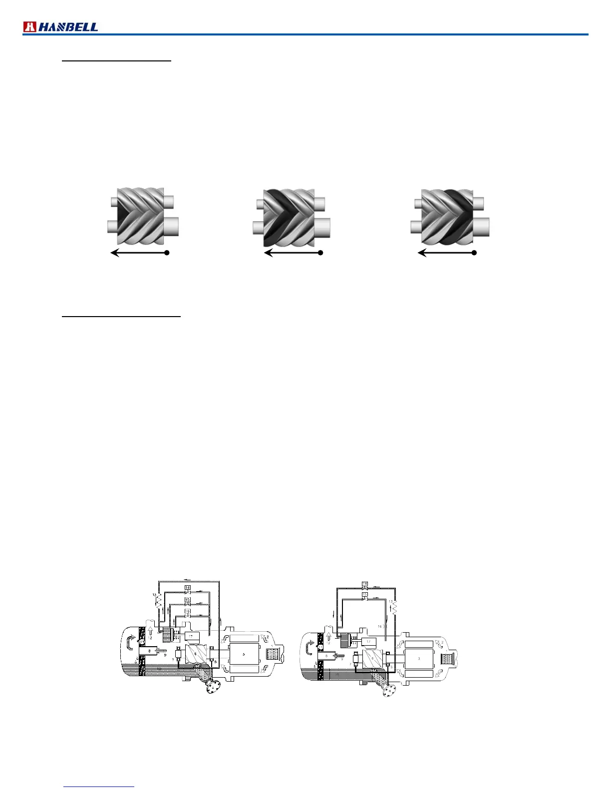
(A) Suction and sealing:
At the beginning of the compression cycle, as the male rotor and female rotor unmesh, gas from suction port fills
the interlobe space (refer to the dark area below). Refrigerant at suction pressure continues to fill it, until the trailing
lobe crosses the suction area and the gas is trapped inside the interlobe space.
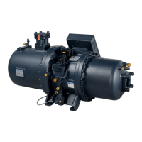
(B) Compression:
As the male rotor and female rotor meshes, the interlobe space moves towards to discharge end and its volume
decreases so that gas pressure increases consequently.
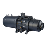
(C) Discharge:
Gas is discharged from the interlobe space when the leading lobe crosses the discharge port whose volume ratio is
designed differently for various applications.
Figure 6 Compression process
2.6 Capacity control system
The RC2 series screw compressors are equipped with either 3step/4step capacity control system or continuous (step
less) capacity control system. Both of the capacity control systems consist of a modulation slide valve, piston rod,
cylinder, piston and piston rings. The slide valve and the piston are connected by a piston rod. The principle of
operation is using the oil pressure to drive the piston in the cylinder. See Figure 7, the lubrication oil flows from the oil
sump through the oil filter cartridge and capillary then fills into the cylinder due to the positive oil pressure bigger than
the right side of spring force plus the high pressure gas. The positive pressure differential causes the piston to move
toward the right side in the cylinder. When the slide valve moves toward the right side, the effective compression
volume in the compression chamber increases. This means the displacement of refrigerant gas also increases, as a
result the refrigeration capacity also increases. However, when any of the step solenoid valve (for 3step/4step
capacity control system) is opened, the high pressure oil in the cylinder bypasses to the suction side, which causes the
piston and the slide valve to move toward the left side, and then some of the refrigerant gas bypasses from the
compression chamber back to the suction end. As a result, the refrigeration capacity decreases because of the
reduction of displacement of refrigerant gas flowing in the system.
The piston spring is used to push the piston back to its original position, i.e. minimum load position in order to reduce
the starting current for the next starting. If the compressor started at full load capacity it may result in over current start.
The capillary is used to maintain and restrain a suitable amount of oil flow into the cylinder. The modulation (stepless)
solenoid valves (SV1 and SV2) are controlled by a micro controller or temperature switch to modulate the piston
position smoothly with stable output of capacity.
If the oil filter cartridge, capillary, or modulation solenoid valves are not working well in the capacity control system, this
may result in the abnormality and ineffectiveness of the capacity control system. Before stopping the compressor,
HANBELL strongly recommends that the unloading solenoid valve of stepless control system or minimum
load solenoid valve of 3/4step control system should be kept opened for 60~90 seconds so that oil pressure
in the cylinder could be released. When starting the compressor again, it is in unloading position for light duty
start.
4steps capacity control
Stepless capacity control
Figure 7 Capacity control system
(A) Suction and sealing
(
B) Compression
(C) Discharge